Switching device of transformer, and transformer

A switchgear and transformer technology, applied in the direction of transformers, variable transformers, electric switches, etc., can solve the problems of unfavorable transformer layout and high transformer cost

Pending Publication Date: 2019-05-10
SIEMENS TRANSFORMER WUHAN
View PDF10 Cites 0 Cited by
  • Summary
  • Abstract
  • Description
  • Claims
  • Application Information

AI Technical Summary

Problems solved by technology

In the above-mentioned transformer, there are many lead wires of the winding, which is not conducive to the layout of the inner space of the transformer, and also causes the cost of the transformer to be high

Method used


Image

  • Switching device of transformer, and transformer
  • Switching device of transformer, and transformer
  • Switching device of transformer, and transformer

Examples


Embodiment Construction

[0058] In order to have a clearer understanding of the technical features, purposes and effects of the invention, the specific embodiments of the present invention are now described with reference to the accompanying drawings, in which the same reference numerals represent components with the same or similar structures but the same functions.

[0059] In this article, "schematic" means "serving as an example, example or illustration", and any illustration or implementation described as "schematic" should not be interpreted as a more preferred or more advantageous Technical solutions.

[0060] In this document, "first", "second", etc. do not indicate their importance or order, but are only used to indicate their differences to facilitate the description of the document.

[0061] In order to make the drawing concise, each drawing only schematically shows the parts related to the present invention, and they do not represent the actual structure of the product. In addition, in orde...


PUM


Abstract

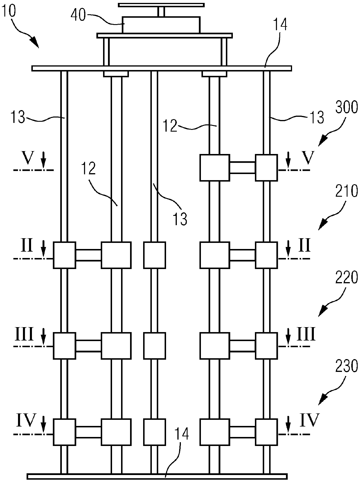
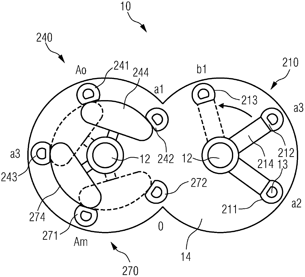
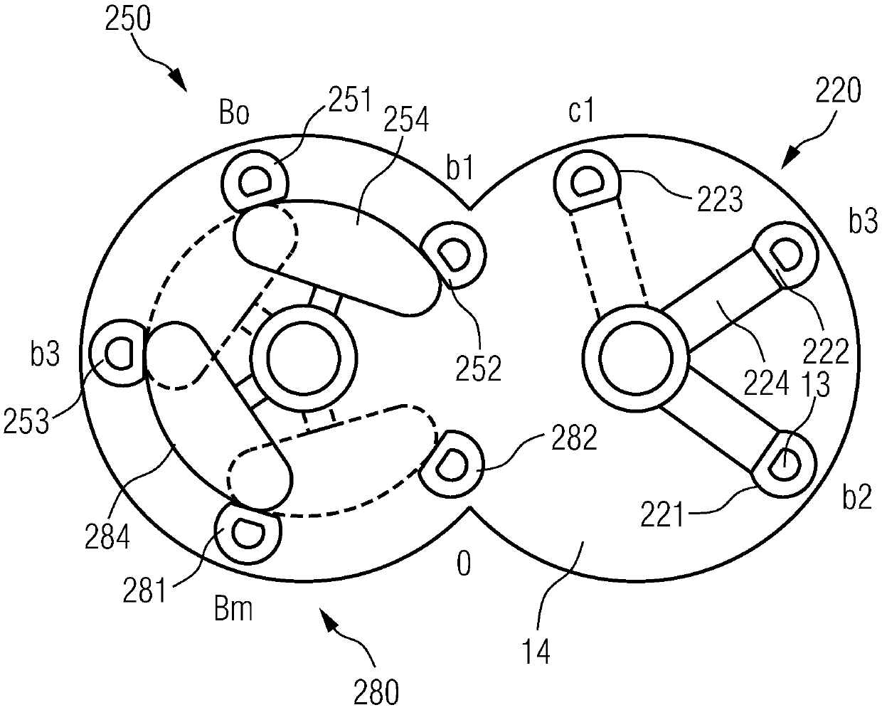
A switching device of a transformer comprises a bracket and a plurality of contact sets, wherein each contact set comprises a common static contact, two tap static contacts, and a moving contact; thecommon static contacts are disposed on the bracket; the tap static contacts are disposed on the bracket and sequentially disposed in a circumferential direction; the moving contacts are movably disposed on the bracket, the ends of the moving contacts are movable in the circumferential direction, the moving contacts contact the common static contacts and one tap static contact when in a first gear,and the moving contacts contact the common static contacts and the other tap static contact when in a second gear. When the switching device realizes functions, the common static contacts in respective contact sets only need to be connected with one lead wire to eliminate the plurality of lead wires at the same position of the winding, which saves the cost of the transformer, and facilitates theutilization of the internal space of the transformer. The invention also provides a transformer comprising the switching device.

Description

technical field [0001] The invention relates to a switching device, in particular to a switching device for a transformer. The invention also relates to a transformer comprising such a switching device. Background technique [0002] With the development of power systems, transformers are more required to have functions such as variable voltage, variable groups, and variable high-voltage voltage terminals. Current transformers generally include windings with multiple lead wires and several switch devices corresponding to the above-mentioned functions. The above-mentioned functions of the transformer are realized by controlling the on-off between the lead-out wires through the several switch devices. In the above-mentioned transformer, the lead wires of the winding are many, which is not conducive to the layout of the inner space of the transformer, and also causes the cost of the transformer to be high. Contents of the invention [0003] The purpose of the present inventi...

Claims


Application Information

Patent Timeline
Patent Type & Authority Applications(China)
IPC IPC(8): H01H9/00H01F29/02
Inventor 廖威钟孝泰张亚旭吴先威朱德虎周灿文黄先博金宝权
Owner SIEMENS TRANSFORMER WUHAN
Why Eureka
Try Eureka