Material damage detection method and device

A technology of damage detection and all directions, applied in the field of measurement, can solve the problems of limited strain gauge volume and lead mode, affecting the integrity and continuity of the matrix, unable to cover the entire surface of the material, etc. The effect of light weight and simple structure

Pending Publication Date: 2021-02-09
INST OF ENGINEERING THERMOPHYSICS - CHINESE ACAD OF SCI
View PDF0 Cites 0 Cited by
  • Summary
  • Abstract
  • Description
  • Claims
  • Application Information

AI Technical Summary

Problems solved by technology

The optical fiber detection method needs to embed the optical fiber inside the material, and the embedded optical fiber will cause a stress concentration area in the material, affect the integrity and continuity of the matrix, and cause a decline in the mechanical properties of the material
The way of pasting the strain gauge can measure the strain / stress of the local point, but limited by the volume of the strain gauge and the way of the lead wire, it cannot cover the entire surface of the material; when a rupture occurs, if the strain gauge is attached to this position, the strain The chip will be broken and invalid

Method used


Image

  • Material damage detection method and device
  • Material damage detection method and device
  • Material damage detection method and device

Examples


Embodiment Construction

[0047] In order to make the object, technical solution and advantages of the present invention clearer, the present invention will be described in further detail below in conjunction with specific embodiments and with reference to the accompanying drawings.

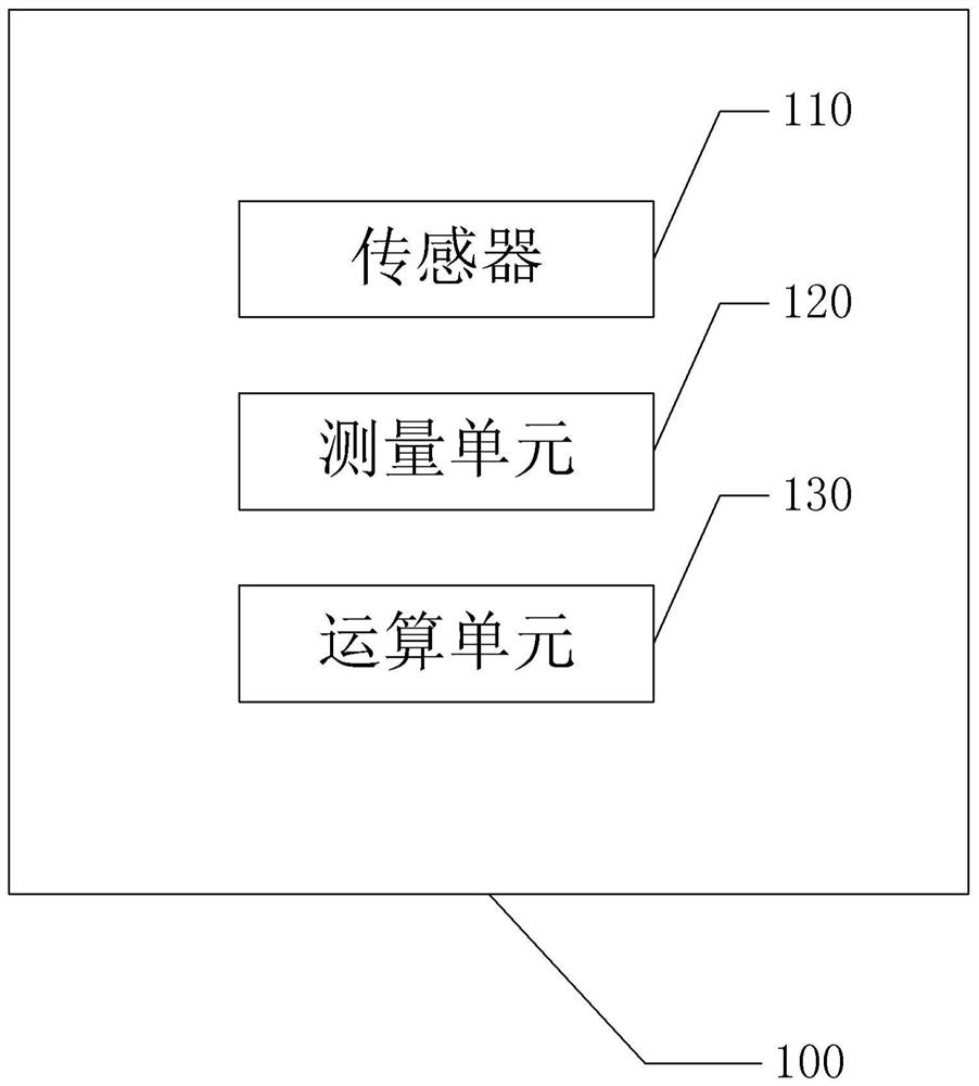
[0048] figure 1 A block diagram of a detection device according to an embodiment of the present invention is schematically shown.

[0049] Such as figure 1 As shown, the embodiment of the present invention provides a material damage detection device, the device 100 includes: a sensor 110, including a conductive layer or a composite film layer containing at least two conductive layers, the conductive layer is consistent with the surface rupture of the material matrix, An insulating layer is arranged between the conductive layers of the composite film layer.

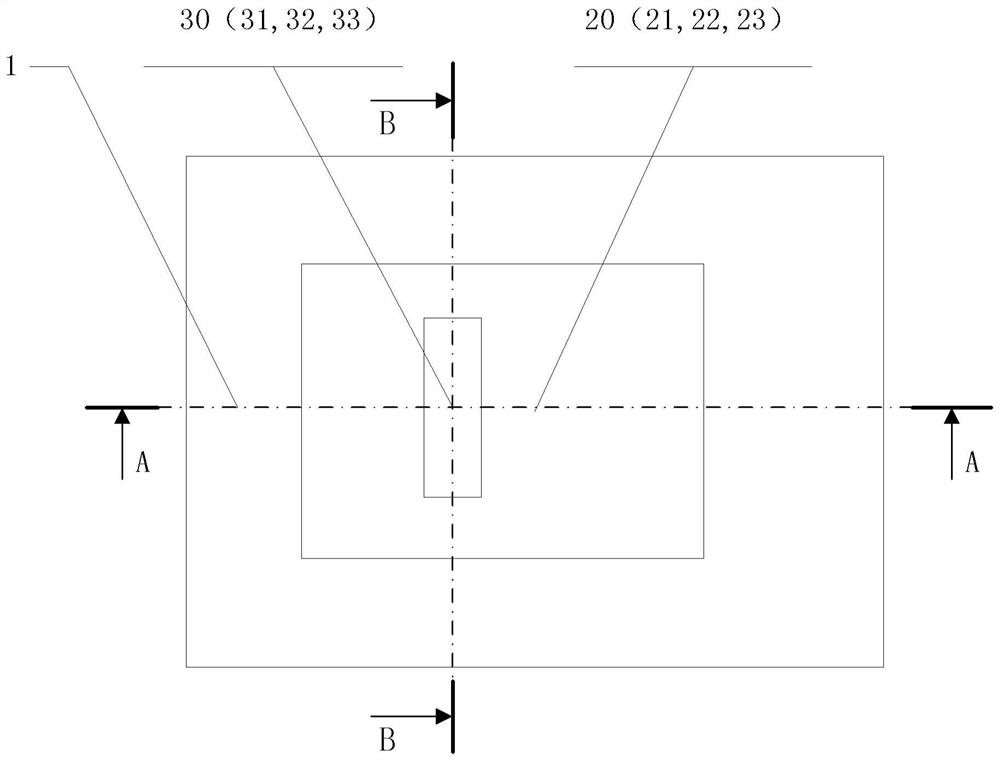
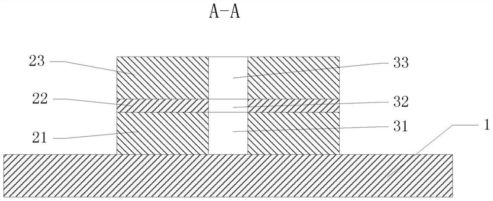
[0050] figure 2 Schematically shows a schematic structural diagram of the sensor according to the first embodiment of the present invention; image 3 schematical...


PUM

PropertyMeasurementUnit
thicknessaaaaaaaaaa
thicknessaaaaaaaaaa
thicknessaaaaaaaaaa

Abstract

The invention provides a material damage detection method and device, and the method comprises the steps: preparing a conductive layer on a material substrate, and enabling the conductive layer to bebroken to the same degree when the surface of the material substrate is broken; introducing current into the conducting layer in at least two different directions, and measuring the variation of the resistance value of the conducting layer in each direction; and calculating the rupture size of the surface of the material matrix according to the variation of the resistance value in each direction.The method and the device achieve high-efficiency and high-precision detection of the fracture and damage conditions of the surface of the material structure body, and are suitable for the surfaces ofvarious detected material matrixes and material matrixes with complex structures and large areas.

Description

technical field [0001] The invention relates to the field of measurement technology, in particular to a material damage detection method and device. Background technique [0002] In order to ensure the normal application of materials as the main components in various occasions, and the requirements for the integrity of material components or structures themselves, especially in aerospace application scenarios, the integrity of material structural parts directly affects the safety and reliability of aircraft. The structural integrity of the material needs to be monitored. [0003] At present, the detection methods for the structural integrity of materials include optical fiber detection, strain gauge detection and other methods. The optical fiber detection method needs to embed the optical fiber inside the material, and the embedded optical fiber will cause a stress concentration area in the material, affect the integrity and continuity of the matrix, and cause a decline in ...

Claims


Application Information

Patent Timeline
Patent Type & Authority Applications(China)
IPC IPC(8): G01N27/04G01B7/00
CPCG01B7/00G01N27/041
Inventor 赵世迁郑会龙康振亚张谭杨肖芳于浩张晓武
Owner INST OF ENGINEERING THERMOPHYSICS - CHINESE ACAD OF SCI
Why Eureka
Try Eureka