Display and display panel thereof

A technology of display panel and display area, which is applied to static indicators, instruments, electric solid-state devices, etc., can solve the problems of difficulty in non-display area, obstacles to the realization of narrow frame design, etc., so as to facilitate narrow frame design and reduce the occupation effect of space

Active Publication Date: 2019-05-10
KUNSHAN GO VISIONOX OPTO ELECTRONICS CO LTD
View PDF5 Cites 8 Cited by
  • Summary
  • Abstract
  • Description
  • Claims
  • Application Information

AI Technical Summary

Problems solved by technology

However, limited by the complex wiring environment of these signal traces, it is very difficult to compress the non-display area, which hinders the realization of narrow bezel design

Method used


Image

  • Display and display panel thereof
  • Display and display panel thereof
  • Display and display panel thereof

Examples


Embodiment Construction

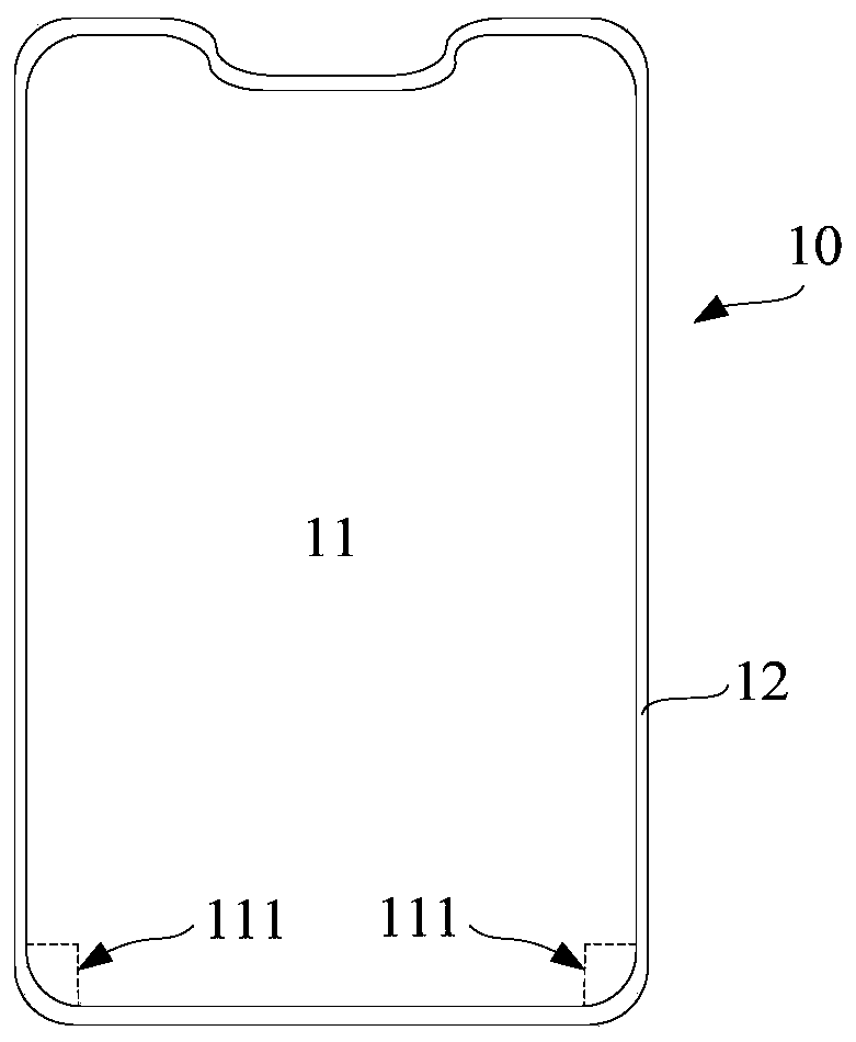
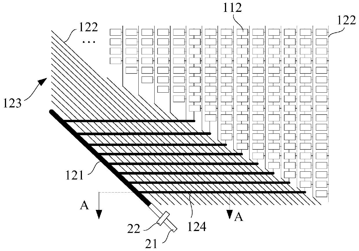
[0011] The primary purpose of this application is to: add a VDD line in the special-shaped display area, which connects to the pixels in the special-shaped display area through multiple conduction lines, and reduces the current difference received by the pixels in the regular display area and the special-shaped display area , so as to avoid the risk of split screen caused by large voltage division impedance. At the same time, only one VDD line is arranged in the special-shaped display area, which occupies a small space in the non-display area, which is beneficial to the narrow frame design.

[0012] Based on the above purpose, the technical solutions in the embodiments of the present application will be clearly and completely described below in conjunction with the drawings of the embodiments of the present application. It should be understood that the specific embodiments described here are only used to explain the present application, but not to limit the present application...


PUM


Abstract

The invention discloses a display and a display panel. A VDD wire is added in a special-shaped display area and the VDD wire is connected with pixels in the special-shaped display area through a plurality of breakover wires, so that benefit is brought to the design of narrow frames and the split screen risk caused by relatively large impedance is avoided.

Description

technical field [0001] The present application relates to the field of display technology, in particular to a display and a display panel thereof. Background technique [0002] From traditional button-type mobile phones to today's touch-type smart phones, mobile phones are increasingly developing in the direction of high screen-to-body ratio, among which full-screen technology is the mainstream in the industry. The full-screen technology can not only increase the visible area of ​​the mobile phone, but also improve the appearance of the mobile phone, making the mobile phone look more technological. In addition, the front area of ​​the fuselage can accommodate a larger screen, which has a significant impact on the visual experience. promote. On this basis, in order to meet the diverse needs of people, at least one corner of the full-screen display panel is usually designed to be shaped, for example, combined with figure 1 As shown, the lower left and right corners of the di...

Claims


Application Information

Patent Timeline
Patent Type & Authority Applications(China)
IPC IPC(8): H01L27/32G09F9/30
CPCG09F9/30G09G3/20G09G2300/0426G09G2330/04H04B1/3827Y02E10/549H01L27/0288H01L27/0296Y02P70/50H10K59/131G06F3/044G09G3/3233G09G2320/0233H01L27/0292H10K59/126H10K77/111H10K2102/311
Inventor 常苗李威龙张露胡思明韩珍珍
Owner KUNSHAN GO VISIONOX OPTO ELECTRONICS CO LTD
Why Eureka
Try Eureka