Stamping mould used for automobile parts

A technology for stamping dies and auto parts, which is applied in the direction of forming tools, manufacturing tools, metal processing equipment, etc. It can solve the problems of consuming a lot of manpower and material resources, uneven force on the mold, and too fast damage to the knife edge, so as to improve production efficiency and improve Strength and the effect of prolonging the service life

Inactive Publication Date: 2019-05-14
十堰昶耀科技服务有限公司
View PDF0 Cites 0 Cited by
  • Summary
  • Abstract
  • Description
  • Claims
  • Application Information

AI Technical Summary

Problems solved by technology

[0002] At present, in the trimming and punching of the same part in the automobile cold stamping die, the structural design needs to be designed in the same sequence. There are many separate punching dies for wheel cover parts, which will cause the upper presser and the overall force of the die to be uneven. The knife edge is damaged too quickly, the punch is easy to undercut and the parts have burrs, etc. The parts often need to be reworked, which consumes a lot of manpower and material resources

Method used


Image

  • Stamping mould used for automobile parts
  • Stamping mould used for automobile parts
  • Stamping mould used for automobile parts

Examples


Embodiment 1

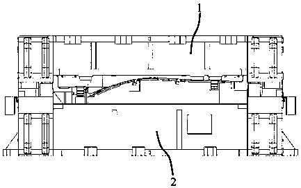
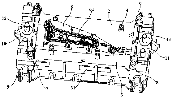
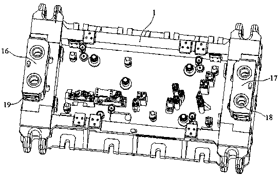
[0019] A stamping die for automobile parts, as shown in accompanying drawings 1 to 3, includes an upper mold pressing material core 1 and a lower mold 2, and the lower mold 2 further includes a lower mold base 3, at least four balance weights 4 and 4 A lifting part 5, the four lifting parts 5 are respectively located at the four corners of the lower mold base 3, the upper surface of the lower mold base 3 has a boss 6, the boss 6 has a workpiece processing area 61, the Among the at least 4 balance weights 4, some of the balance weights 4 are installed on the upper surface of the lower mold base 3 and located on one side of the workpiece processing area 61, and the rest of the balance weights 4 are installed on the upper surface of the lower mold base 3 and located on the other side of the workpiece processing area 61. , the lower mold base 3 is provided with a buffer 7 near the four corners, the buffer 7 is composed of a steel sleeve 8 and a polyurethane cylinder 9 inside the st...

Embodiment 2

[0022] A stamping die for auto parts, comprising an upper mold pressing core 1 and a lower mold 2, the lower mold 2 further includes a lower mold base 3, at least four balance weights 4 and four lifting parts 5, the four The lifting parts 5 are respectively located at the four corners of the lower mold base 3, the upper surface of the lower mold base 3 has a boss 6, and the boss 6 has a workpiece processing area 61, and the middle parts of the at least four balance weights 4 The balance weight 4 is installed on the upper surface of the lower die base 3 and is positioned at one side of the workpiece processing area 61, and the other balance weights 4 are installed on the upper surface of the lower die base 3 and positioned at the other side of the workpiece processing area 61. The lower die base 3 is close to the four sides. Each corner is provided with a buffer 7, which consists of a steel sleeve 8 and a polyurethane cylinder 9 located in the steel sleeve 8. The height of the p...


PUM


Abstract

The invention discloses a stamping mould used for automobile parts. The stamping mould comprises an upper mould pressing core and a lower mould, wherein the lower mould further comprises a lower mouldbase, at least four balance blocks and four lifting parts; height of a polyurethane column body is greater than height of a steel sleeve; a left notch slot and a right notch slot are separately formed in the two ends of the lower mould base; at least two guide columns are arranged in each of the left notch slot and the right notch slot; a lower slide plate is arranged on each of the inner side wall, the front side wall and the rear side wall of each of the left notch slot and the right notch slot; a plurality of through holes are uniformly formed in each lower slide plate in a spaced mode, and graphite columns are embedded into the through holes; the two ends of the upper mould are separately equipped with a left convex slide block and a right convex slide block, and slide sleeves which are fitted to the guide columns are arranged in the left convex slide block and the right convex slide block; upper slide plates which are matched with the lower slide plates are arranged on the outerside wall of the left convex slide block and the outer side wall of the right convex slide block; and a plurality of through holes are uniformly formed in each upper slide plate in a spaced mode, andgraphite columns are embedded into the through holes. Integral balance and buffer of the stamping mould is improved, damages, on materials, of vibrations and strong impact force are reduced, balancedstress during contact is kept, and damage speed of the mould is also reduced.

Description

technical field [0001] The invention relates to a stamping die used for automobile parts, belonging to the technical field of stamping dies. Background technique [0002] At present, in the trimming and punching of the same part in the automobile cold stamping die, the structural design needs to be designed in the same sequence. There are many separate punching dies for wheel cover parts, which will cause the upper presser and the overall force of the die to be uneven. The knife edge is damaged too quickly, the punch is easy to undercut and the parts have burrs, etc. The parts often need to be reworked, which consumes a lot of manpower and material resources. Contents of the invention [0003] The object of the present invention is to provide a stamping die for automobile parts, which improves the overall balance and buffering of the stamping die, reduces the damage to the material caused by vibration and strong impact force, and at the same time, maintains the impact resi...

Claims


Application Information

Patent Timeline
Patent Type & Authority Applications(China)
IPC IPC(8): B21D37/10B21D37/18
Inventor 赵虎
Owner 十堰昶耀科技服务有限公司
Why Eureka
Try Eureka