
Dual motor and fan with dual motor

A dual-motor, motor technology, applied in the control of mechanical energy, non-variable-capacity pumps, electric components, etc., can solve the problem of inability to switch between large-scale and small-scale air flow

Pending Publication Date: 2019-05-14
SUNONWEALTH ELECTRIC MACHINE IND
View PDF8 Cites 1 Cited by
  • Summary
  • Abstract
  • Description
  • Claims
  • Application Information

AI Technical Summary

Problems solved by technology

[0003] The rotation speed and torque of the above-mentioned existing motors can be adjusted, but limited by the fixed specifications of the rotor and stator, the motor has an adjustable range, so the fan blades that can be combined and driven by the motor must match the specifications of the motor, which can only be achieved Limited efficiency, so a single motor combined with a set of fans cannot switch between large-scale and small-scale air flow according to the situation

Method used


Image

  • Dual motor and fan with dual motor
  • Dual motor and fan with dual motor
  • Dual motor and fan with dual motor

Examples


Embodiment Construction

[0051] In order to make the above and other purposes, features and advantages of the present invention more comprehensible, the preferred embodiments of the present invention are listed below, together with the accompanying drawings, as follows:

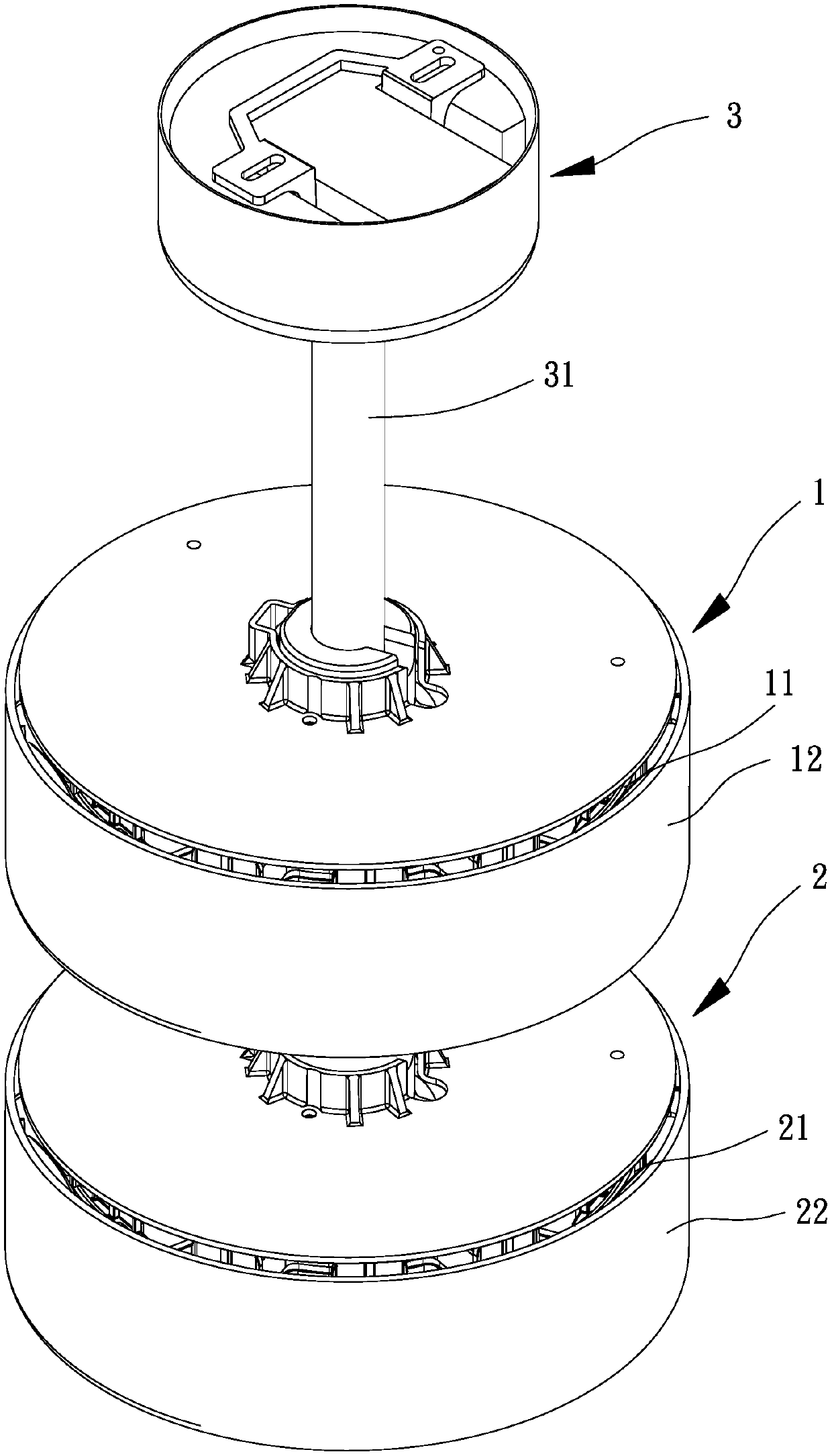
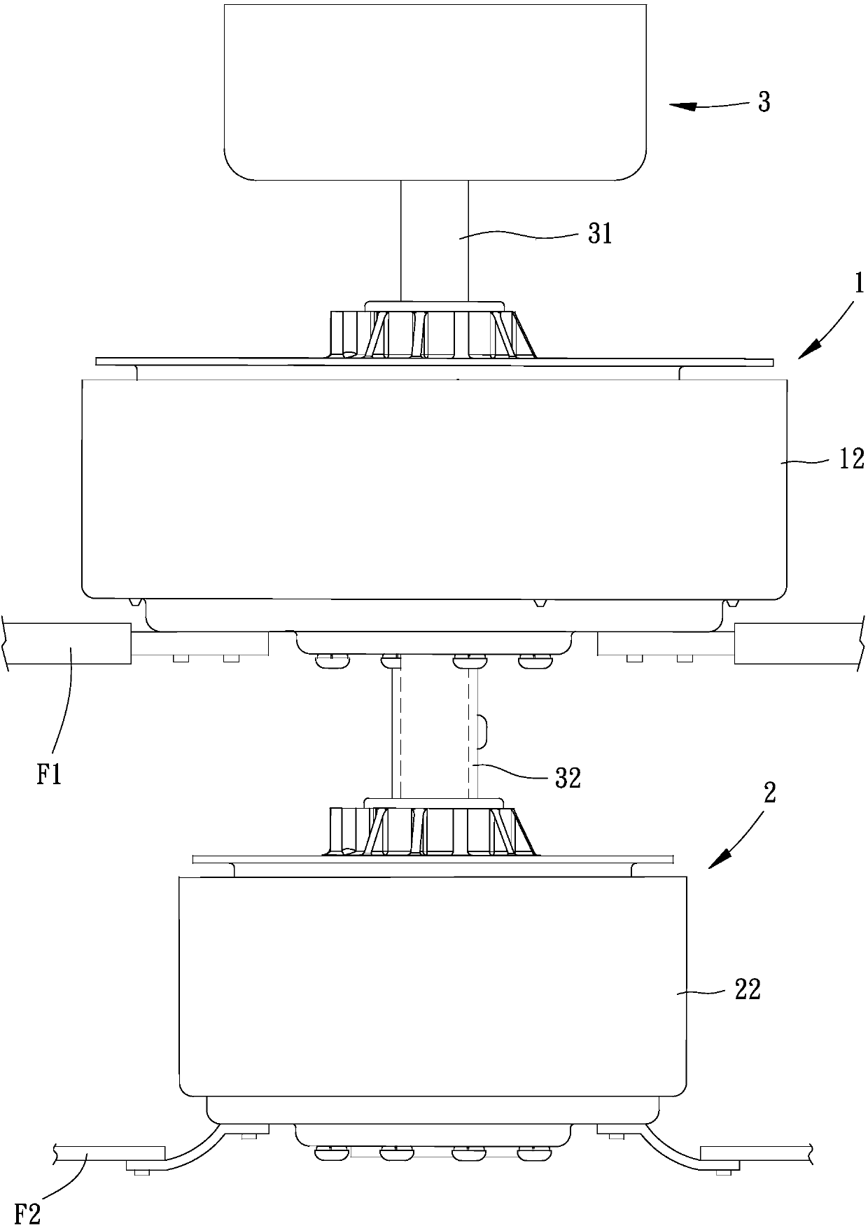
[0052] Please refer to figure 1 As shown, it is the first embodiment of the present invention. The coaxial dual motor includes a first motor 1, a second motor 2 and a positioning assembly 3, and the positioning assembly 3 is coaxially connected to the first motor 1 and the The second motor 2.

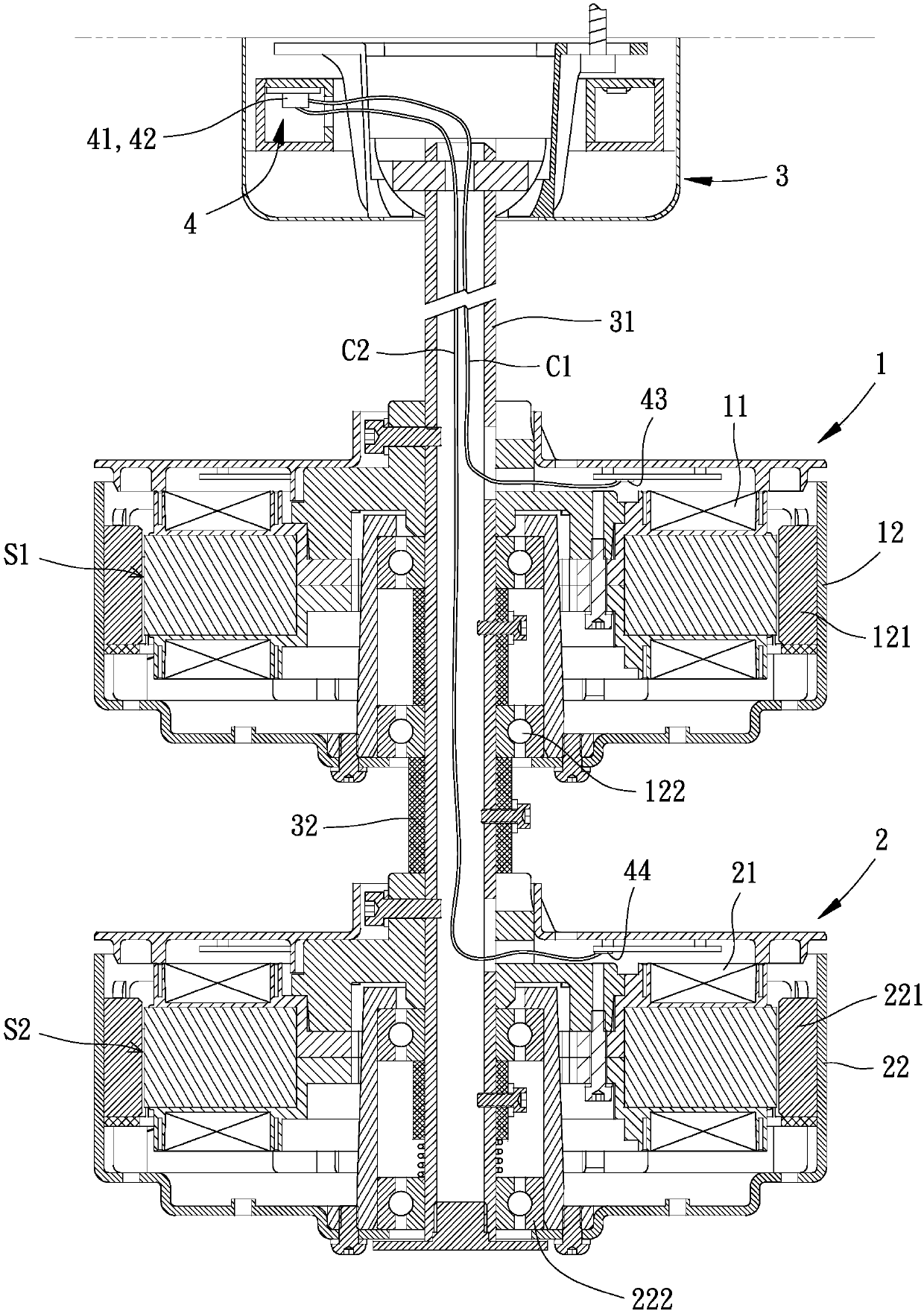
[0053] Please refer to figure 2 As shown, the first motor 1 includes a first stator 11 and a first rotor 12 , and the first rotor 12 forms a first accommodating space S1 for accommodating the first stator 11 . The first rotor 12 further includes a first permanent magnet set 121 and a bearing 122 .

[0054] The second motor 2 includes a second stator 21 and a second rotor 22 , and the second rotor 22 forms a second accommodating space S2 fo...


PUM


Abstract

The invention provides a dual motor and a fan with a dual motor, and aims to solve the problem that the functions of a conventional motor and a fan are always the same. The dual motor comprises a first motor, which comprises a first stator and a first rotor; a second motor, which comprises a second stator and a second rotor; a positioning assembly, which comprises a central shaft that penetrates the first motor and the second motor; and a driving circuit, which is electrically connected to the first stator and the second stator. The first rotor and the second rotor are rotatingly combined withthe central shaft. The first stator and the second stator are fixedly combined with the central shaft. The first rotor comprises a first permanent magnet set. The second rotor comprises a second permanent magnet set.

Description

technical field [0001] The invention relates to a dual motor and a fan with the dual motor, in particular to a dual motor that can rotate simultaneously or alternately and the fan with the dual motor. Background technique [0002] The existing motor can be combined with a group of fan blades to supply or exhaust air to a space, and the motor speed is controlled to adjust the wind speed and air volume generated by the fan blades, which has the effect of air circulation. [0003] The rotation speed and torque of the above-mentioned existing motors can be adjusted, but limited by the fixed specifications of the rotor and stator, the motor has an adjustable range, so the fan blades that can be combined and driven by the motor must match the specifications of the motor, which can only be achieved Limited efficiency, so a single motor combined with a set of fans cannot switch between large-scale and small-scale air flow according to the situation. [0004] In view of this, the ex...

Claims


Application Information

Patent Timeline
IPC IPC(8): F04D25/08H02K7/14
Inventor 洪银树邱柏伟
Owner SUNONWEALTH ELECTRIC MACHINE IND
Learn More