Load damping rotating mechanism

A rotating mechanism and damping technology, which is applied in the direction of supporting machines, mechanical equipment, machine platforms/supports, etc., can solve problems that endanger the stability and vibration of military control and display systems

Inactive Publication Date: 2019-05-14
中航华东光电有限公司
View PDF5 Cites 0 Cited by
  • Summary
  • Abstract
  • Description
  • Claims
  • Application Information

AI Technical Summary

Problems solved by technology

[0002] The control and display system in the military field is developing more and more rapidly. In order to meet the needs of different viewing angles of operators, the display system needs to have the functions of adjusting direction and reset. Because the milit

Method used


Image

  • Load damping rotating mechanism
  • Load damping rotating mechanism

Examples


Embodiment Construction

[0020] Specific embodiments of the present invention will be described in detail below in conjunction with the accompanying drawings. It should be understood that the specific embodiments described here are only used to illustrate and explain the present invention, and are not intended to limit the present invention.

[0021] In the present invention, in the absence of a contrary description, the orientation words included in the term, such as "upper, lower, inner, side", etc., only represent the orientation of the term in the normal use state, or are understood by those skilled in the art colloquial term and should not be construed as a limitation of the term.

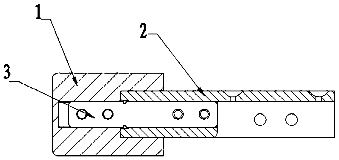
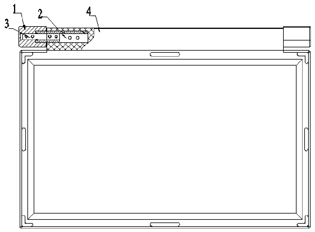
[0022] Such as figure 1 , figure 2 As shown, the present invention provides a load-bearing damping rotating mechanism, including a shaft sleeve 1, a rotating shaft 2 and a rotation damping member 3, including a shaft sleeve 1, a rotating shaft 2 and a rotation damping member 3, and the shaft sleeve 1 is sequentiall...


PUM


Abstract

The invention discloses a load damping rotating mechanism. The load damping rotating mechanism comprises a shaft sleeve, a rotating shaft and a rotary damping piece, the shaft sleeve is sequentially provided with a first stepped hole and a second stepped hole in order from the outside to the inside; one end of the rotating shaft is connected into the first stepped hole in a sleeved manner and canrotate around the axial rotation of the rotating shaft, the side wall of the other end is fixedly connected with a mechanism to be rotated, and the end, connected into the first stepped hole in a sleeved manner, of the rotating shaft is further provided with an axial mounting hole; and the rotatable end of the rotary damping piece is arranged in the axial mounting hole, and the other rotatable endis arranged in the second stepped hole. The mechanism can be used for direction adjustment and resetting of military control display systems and remains stable in the direction adjustment and resetting process.

Description

technical field [0001] The invention relates to a control and display system installation component, in particular to a load damping rotation mechanism. Background technique [0002] The control and display system in the military field is developing more and more rapidly. In order to meet the needs of different viewing angles of operators, the display system needs to have the functions of adjusting direction and reset. Because the military control and display system has high requirements for vibration and impact, after conventional direction adjustment Due to the effect of inertia, relatively large vibrations may occur, seriously endangering the stability of the military control display system. [0003] Therefore, how to provide a mechanism for adjusting and resetting the direction of the military control display system, and how to keep it stable during the direction adjustment and resetting process is an urgent problem to be solved at present. Contents of the invention ...

Claims


Application Information

Patent Timeline
IPC IPC(8): F16C11/04F16C11/10F16M11/06B60R11/02
Inventor 徐钧王杰朱标黄震凌周文雅
Owner 中航华东光电有限公司
Why Eureka
Try Eureka