
Oil-gas separation device for testing oil-gas separation efficiency of engine

A technology of separation device and separation efficiency, which is applied in the direction of internal combustion engine testing, etc., can solve the problems of poor oil-gas separation accuracy and inability to test oil-gas separation efficiency, and achieve the effects of low manufacturing cost, high accuracy of test results, and increased impact probability

Inactive Publication Date: 2019-05-14
YIBIN COWIN AUTO CO LTD
View PDF9 Cites 2 Cited by
  • Summary
  • Abstract
  • Description
  • Claims
  • Application Information

AI Technical Summary

Problems solved by technology

The device has poor accuracy in testing oil and gas separation, and because the gas outlet of the oil analysis bottle is directly the same as the atmosphere, it is impossible to test the oil and gas separation efficiency under the normal crankcase pressure of the engine

Method used


Image

  • Oil-gas separation device for testing oil-gas separation efficiency of engine
  • Oil-gas separation device for testing oil-gas separation efficiency of engine

Examples


Embodiment Construction

[0033] In the present invention, it should be understood that the terms "length", "width", "upper", "lower", "front", "rear", "left", "right", "vertical", "horizontal" ", "Top", "Bottom", "Inner", "Outer", "Clockwise", "Counterclockwise", "Axial", "Plane Direction", "Circumferential" and other indications are based on The orientation or positional relationship shown in the drawings is only for the convenience of describing the present invention and simplifying the description, and does not indicate or imply that the referred device or element must have a specific orientation, be constructed and operated in a specific orientation, and therefore cannot be understood as Limitations on the Invention.

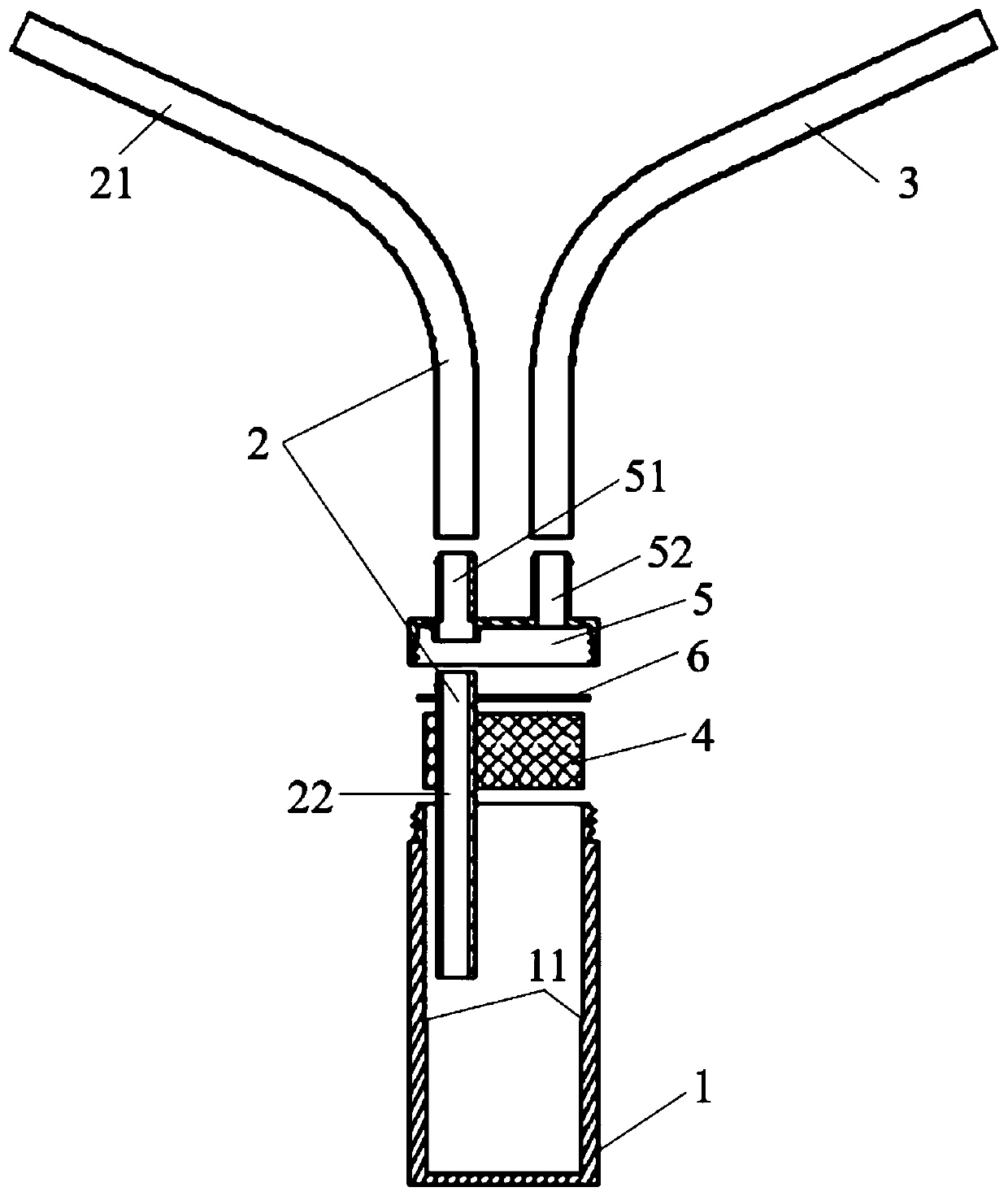
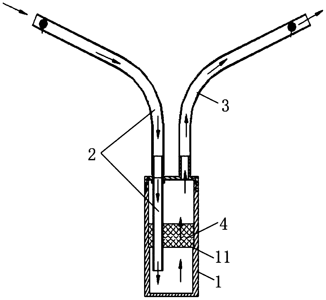
[0034] Such as figure 1 , figure 2 As shown, an oil-gas separation device for testing the oil-gas separation efficiency of an engine includes an oil analysis bottle 1, an air intake pipe 2, an air outlet pipe 3 and a sponge 4, the sponge 4 is arranged in the oil analysis bottle 1...


PUM


Abstract

The invention discloses an oil-gas separation device for testing the oil-gas separation efficiency of an engine. The device comprises an oil separation bottle, a gas inlet pipe, a gas outlet pipe andsponge; the sponge is arranged in the oil separation bottle; the gas inlet pipe is inserted into the oil separation bottle and penetrates through the sponge; and the gas outlet pipe is inserted into the oil separation bottle and is located above the sponge. A cavity of the oil separation bottle is divided into an upper layer and a lower layer through the sponge; the gas inlet pipe passes through the sponge to penetrate into the lower layer; gas introduced into the oil separation bottle through the gas inlet pipe directly enters the lower part of the sponge; a gas inlet of the gas outlet pipe is located at the upper layer, namely, above the sponge; and the gas introduced into the oil separation bottle needs to pass through the sponge and can be discharged through the gas outlet pipe. According to the oil-gas separation device, oil drops in the gas are adhered through the sponge, and the impact probability of the oil drops is greatly improved compared with a traditional oil separation bottle, so that the accuracy of testing the oil-gas separation efficiency of the engine is improved. The invention further provides a method for testing the oil-gas separation efficiency of the engine.

Description

technical field [0001] The invention belongs to the technical field of engine testing, and in particular relates to an oil-gas separation device and a test method for testing the oil-gas separation efficiency of an engine. Background technique [0002] At present, when testing the oil-gas separation efficiency of the engine, the oil separation bottle is connected in series between the engine flex pipes, so that the crankcase blow-by gas is discharged into the atmosphere through the oil separation bottle, and the oil droplets (diameter 0.1 μm) in the blow-by gas are not separated inside the engine ~10μm in diameter) partly impacts on the inner wall of the oil analysis bottle under the action of inertia, so as to realize the separation; after the test, the oil analysis bottle is baked, and the total amount of the oil analysis bottle increased per unit time is the engine oil-gas separation efficiency. [0003] The existing separation device only relies on the impact of oil drop...

Claims


Application Information

Patent Timeline
Patent Type & Authority Applications(China)
IPC IPC(8): G01M15/04
Inventor 田文化易佑松何林杰贾安通张礼兵
Owner YIBIN COWIN AUTO CO LTD
Learn More