Clothes zipper

A zipper and clothing technology, applied in the field of clothing zipper, can solve the problems of inability to replace, inconvenient to use, damaged zipper, etc.

Inactive Publication Date: 2019-05-17
颍上县艺豪服饰辅料有限公司
View PDF15 Cites 1 Cited by
  • Summary
  • Abstract
  • Description
  • Claims
  • Application Information

AI Technical Summary

Problems solved by technology

[0004] The handle of the existing zipper cannot be replaced. When the handle is damaged, the zipper will be damaged and cannot be replaced, which is not only inconvenient to use, but also affects the aesthetics of the object

Method used


Image

  • Clothes zipper
  • Clothes zipper
  • Clothes zipper

Examples


Embodiment 1

[0027] Such as Figure 5-6 Shown, a kind of clothes zipper comprises slider 4, and slider 4 comprises locking part 8 and pull handle 19, and locking part 8 comprises main body and arc-shaped part 11, and one end outside the main body of locking part 8 is fixed with a number Fixed block 10, one end of arc-shaped part 11 is connected No. 1 fixed block 10 by connecting pin 12, and the other end of arc-shaped part 11 is free end, and No. 2 fixed block 13 is fixed on the inner wall of this end, No. 2 fixed block 13 A No. 1 compression spring 14 is fixed at an end away from the arc-shaped member 11, and a clamping block 16 is fixed at an end of the No. 1 compression spring 14 away from the No. 1 fixed block 10, and an end near the No. 1 fixed block 10 on the locking member 8 is fixed with a The connecting plate 15 is provided with a connecting hole, and the fastening block 16 is disposed through the connecting hole.

[0028] In this embodiment, by connecting the main body of the ar...

Embodiment 2

[0030] Such as Figure 5-6 As shown, a No. 2 compression spring 17 is fixed on the inner wall of the arc 11 close to the No. 1 fixed block 10, and a locking rod 18 is fixed on the end of the No. 2 compression spring 17 away from the arc 11. An insertion hole is opened on a side of the main body close to the arc-shaped member 11 , and a locking rod 18 is disposed through the insertion hole; a baffle is fixed between the locking rod 18 and the connecting plate 15 .

[0031] In this embodiment, No. 2 compression spring 17 is set on the inner wall of arc-shaped part 11, and locking rod 18 is set on No. 2 compression spring 17, and then a socket is opened on the main body of locking part 8, so that the lock can be The tightening rod 18 extends into the chain tooth groove 9, and when the slide fastener is used again, the locking rod 18 can lock the chain tooth 3, so as to prevent the slider from sliding down after use, thereby affecting the use of the slide fastener.

Embodiment 3

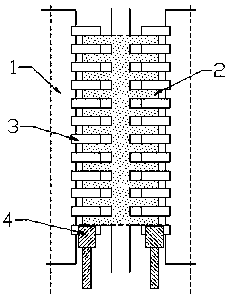
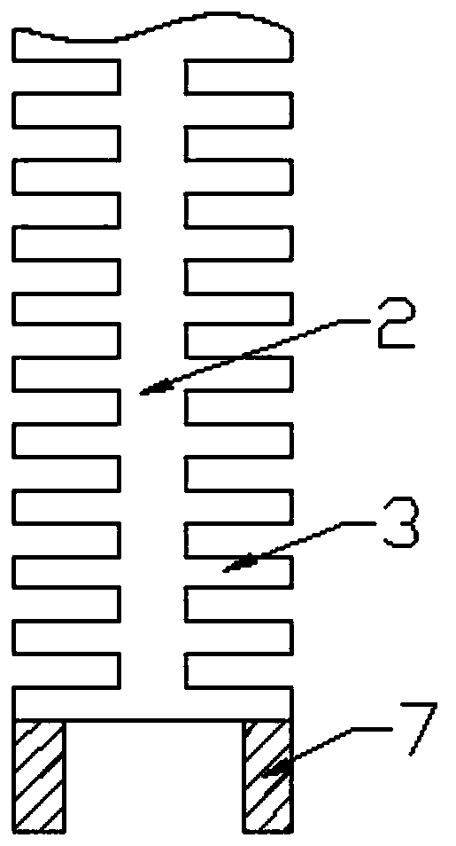
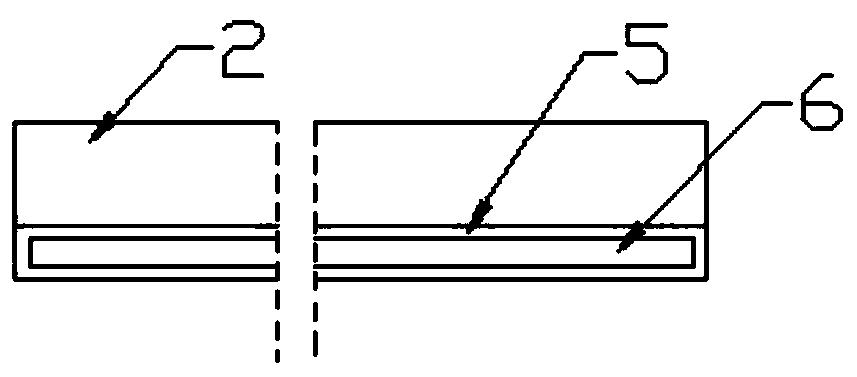
[0033] Such as Figure 1-4 As shown, two sliders 4 are respectively connected to the chain teeth 3 on both sides of the detachable part 2, the back of the detachable part 2 is fixed with a fixed piece 5, and the cross section of the fixed piece 5 is provided with a chain belt groove 6, The chain belt 1 passes through the chain belt groove 6; the chain elements 3 on both sides of the detachable part 2 are respectively connected to the other half of the chain elements 3 corresponding to it, and the chain elements 3 on this side are all fixed on the chain belt 1; The top and bottom ends of the teeth 3 are respectively fixed with an upper stop and a lower stop 7, and the main body of the locking member 8 is provided with a chain tooth groove 9.

[0034] In this embodiment, by setting the detachable part 2 and setting the chain elements 3 on both sides of the detachable part 2, other chain elements 3 can be connected through the chain elements 3 on both sides, so that the slide fas...


PUM


Abstract

The invention discloses a clothes zipper. The clothes zipper comprises a zipper head, wherein the zipper head comprises a locking component and a zipper handle, the locking component comprises a mainbody and an arc-shaped component; a fixing block 1 is fixed to one end of the outer side of the main body of the locking component; one end of the arc-shaped component is connected with the fixing block 1 through a connecting pin; the other end of the arc-shaped component is a free end, and a fixing block 2 is fixed to the inner wall of the free end; a compression spring 1 is fixed to one end, away from the arc-shaped component, of the fixing block 2; a fixedly clamping block is fixed to one end, away from the fixing block 1, of the compression spring 1; a connecting plate is fixed to one end,near the fixing block 1, of the locking component; a connecting hole is formed in the connecting plate; the fixedly clamping block runs through the connecting hole; and through connection of the arc-shaped component and the main body of the locking component by virtue of the connecting pin, the arc-shaped component can be opened, and thus the zipper handle can be detached, so that people can replace the zipper handle conveniently, and when the zipper handle is damaged, inconvenience in use due to incapability of detaching the zipper handle is avoided.

Description

technical field [0001] The invention relates to the field of clothing accessories, in particular to a clothing zipper. Background technique [0002] A zipper is a part that temporarily joins two pieces of fabric together, and is commonly found in clothing, suitcases, handbags, tents, and sleeping bags. [0003] The zipper is composed of chain teeth, sliders, upper and lower stops (front code and rear code) or locking pieces. Among them, the chain teeth are the key part, which directly determines the side pull strength of the zipper. Generally, the zipper has two chain belts, and each chain belt has a row of chain teeth respectively, and the two rows of chain teeth are arranged alternately. The slider clamps the chain elements on both sides, and slides with the help of the pull tab, so that the chain elements on both sides can be engaged or disengaged from each other. Traditional zippers mainly include nylon zippers, resin zippers and metal zippers. [0004] The handle of...

Claims


Application Information

Patent Timeline
Patent Type & Authority Applications(China)
IPC IPC(8): A44B19/26A44B19/24A44B19/30
Inventor 易友志
Owner 颍上县艺豪服饰辅料有限公司
Why Eureka
Try Eureka