Torsion-resistant pull rod structure of power assembly

A technology of anti-torsion tie rod and powertrain, which is applied in the direction of power plant, jet propulsion device, internal combustion propulsion device, etc. It can solve the problems affecting the performance of torsion tie rod, NVH performance, and small surface friction coefficient, so as to improve NVH performance , enhance the stability of the connection, and the effect of gentle stiffness curve

Active Publication Date: 2019-05-17
DONGFENG MOTOR CORP HUBEI
View PDF8 Cites 6 Cited by
  • Summary
  • Abstract
  • Description
  • Claims
  • Application Information

AI Technical Summary

Benefits of technology

This patented technology reduces the stiffer rigidity (the strength) of certain parts within vehicles by making them thinner or lighter than usual for better shock absorption while also enhancing their ability to absorb energy from impact events without causing damage. Additionally, it increases the durability of these components due to improved connections that prevent excessive movement caused by external forces such as collisions. Overall, this innovation helps reduce noise levels inside cars more effectively.

Problems solved by technology

This patented describes how torsionally mounted components are designed for vehicles such as cars or truck engines. These systems have some technical problem addressed through their design: reducing vibrations caused by these sources while still maintaining effective operation over time without causing damage.

Method used


Image

  • Torsion-resistant pull rod structure of power assembly
  • Torsion-resistant pull rod structure of power assembly
  • Torsion-resistant pull rod structure of power assembly

Examples


Embodiment Construction

[0027] The present invention will be further described in detail below in conjunction with the accompanying drawings to facilitate a clearer understanding of the present invention, but they do not limit the present invention.

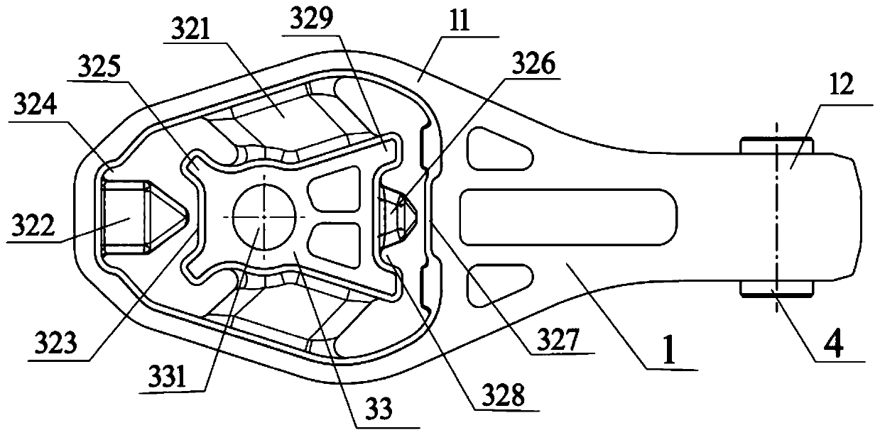
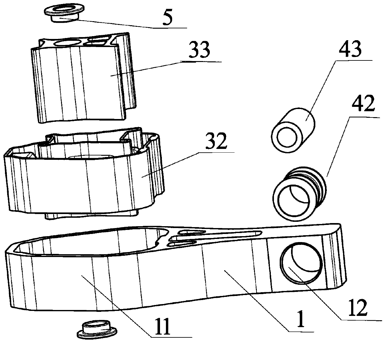
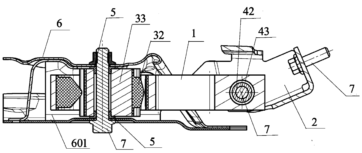
[0028] Such as Figure 1-6 As shown, a powertrain anti-torsion tie rod structure includes a torsion tie rod skeleton 1, and two ends of the torsion tie rod skeleton 1 are respectively provided with a hollow large bushing installation sleeve 11 and a small bushing installation sleeve 12, and the large bushing is installed The sleeve 11 is fixedly connected with a large bush 3, and the small bush installation sleeve 12 is fixedly connected with a small bush 4. The large bush 3 includes a large bush rubber ring 32 and a large bush inner lining 33. The large bush rubber The ring 32 is located between the large bush installation sleeve 11 and the large bush inner lining 33 and is fixed as a whole by vulcanization. The small bush 4 includes a small bush rubbe...


PUM


Abstract

The invention discloses a torsion-resistant pull rod structure of a power assembly. The torsion-resistant pull rod structure of the power assembly comprises a torsion-resistant pull rod framework, wherein the two ends of the torsion-resistant pull rod framework are respectively provided with a large bushing and a small bushing; the large bushing comprises a large bushing rubber ring and a large bushing liner; the large bushing rubber ring is provided with a forward gear rubber impact block and a reverse gear rubber impact block; the ends of the forward gear rubber impact block and the reversegear rubber impact block are tapered; the two sides of the forward gear rubber impact block are provided with forward gear impact block buffer grooves; and two sides of the reverse gear rubber impactblock are provided with reverse gear impact block buffer grooves. According to the invention, the rigidity curves of an initial section and an end section in an acceleration process of a three-gear area are smooth, and abrupt change of rigidity does not exist, so that the vibration strength is reduced, and the NVH performance of a whole vehicle is improved; and a special gasket is arranged betweenthe large bushing liner and a front auxiliary frame assembly, and a small bushing rubber ring is provided with a limiting boss and a buffer groove, so that the connection stability of the two ends ofa torsion-resistant pull rod is enhanced.

Description


Claims


Application Information

Patent Timeline
Owner DONGFENG MOTOR CORP HUBEI
Why Eureka
Try Eureka