[0025] The following will clearly and completely describe the technical solutions in the embodiments of the present invention with reference to the accompanying drawings in the embodiments of the present invention. Obviously, the described embodiments are only some, not all, embodiments of the present invention.
[0026] In describing the present invention, it should be understood that the terms "center", "length", "width", "thickness", "upper", "lower", "front", "rear", "left", " The orientation or positional relationship indicated by "right", "vertical", "horizontal", "top", "bottom", "inner", "outer", etc. is based on the orientation or positional relationship shown in the drawings, and is only for the convenience of description The present invention and simplified description do not indicate or imply that the device or element referred to must have a specific orientation, be constructed and operate in a specific orientation, and thus should not be construed as limiting the present invention.
[0027] In the present invention, terms such as "installation", "installation", "connection", "connection" and "fixation" should be interpreted in a broad sense, for example, it may be a fixed connection or It is a detachable connection; it may be a mechanical connection; it may be a direct connection or an indirect connection through an intermediary. Those of ordinary skill in the art can understand the specific meanings of the above terms in the present invention according to specific situations.
[0028] see Figure 1-4 , the present invention provides a technical solution:
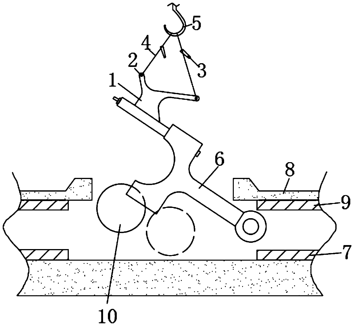
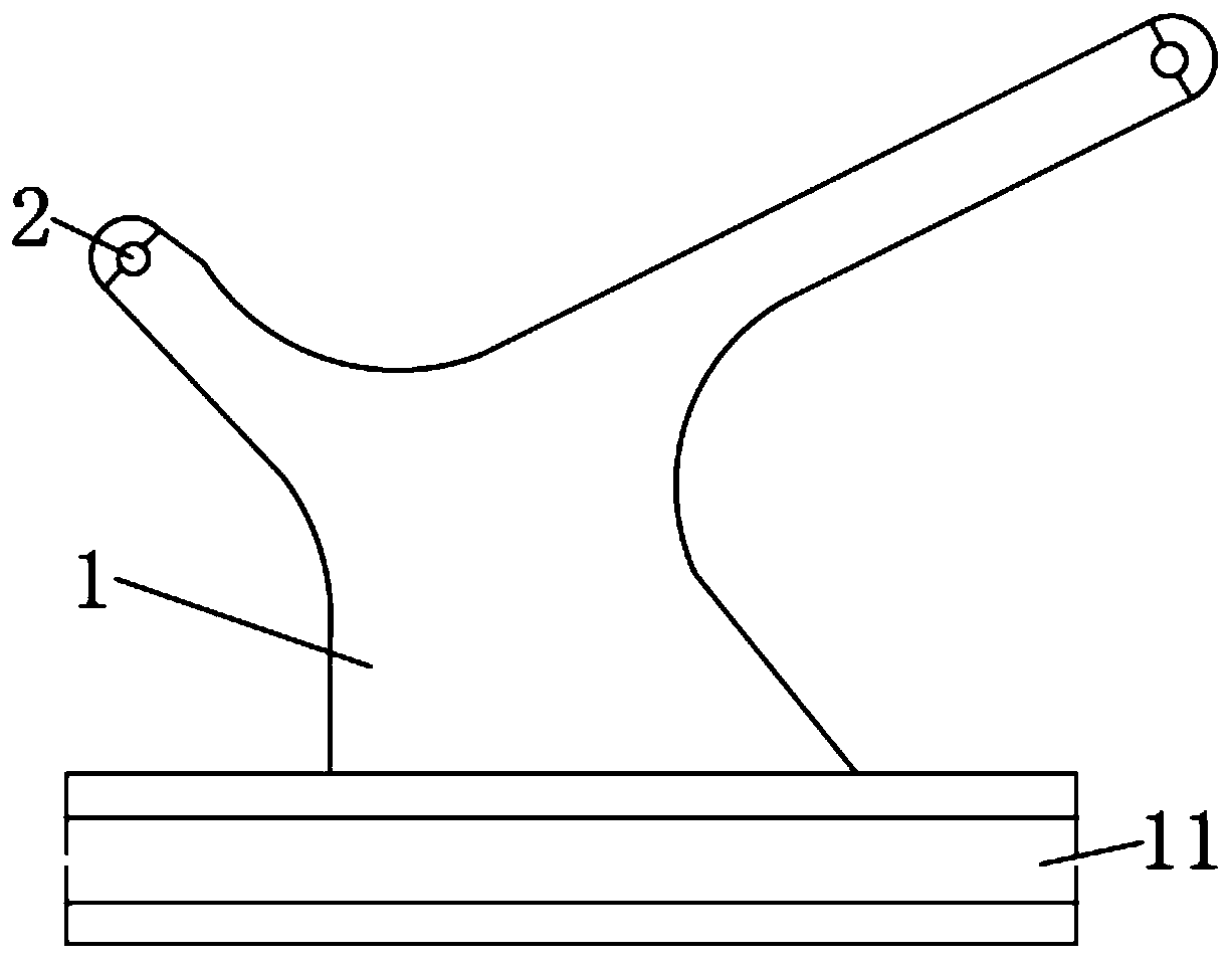
[0029] A balanced hoisting device for irregular components in the inner cavity of a fuselage, comprising an I-shaped spreader 1, a connecting rod 6 and a fuselage 8, and both ends of the top of the I-shaped spreader 1 are equipped with lifting points 2, two lifting points 2 The interiors of the two suspension ropes 4 are fixedly connected with a lifting hook 5, and the tops of the two suspension ropes 4 are movably connected with a lifting hook 5, and the middle parts of the two suspension ropes 4 are fixedly connected with a lever block 3;
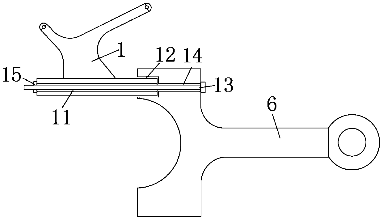
[0030] One side of the bottom of the I-shaped spreader 1 is provided with a perforation 11, and the perforated hole 11 runs through the two sides of the bottom of the I-shaped spreader 1. The top of one end of the connecting rod 6 is provided with a positioning groove 12, and one side of the positioning groove 12 is provided with a screw thread. Hole 14, threaded hole 14 and perforated hole 11 are all equipped with screw rod 13, and one end of screw rod 13 passes through threaded hole 14 and perforated hole 11 and is fixedly connected with nut 15, which can improve the safety of unit installation and maintenance, and reduce the Quality accidents caused by various factors, stably improve the quality of unit installation and unit maintenance, completely overcome the time-consuming and labor-intensive problems of installation, at the same time reduce the work intensity, save manpower and material resources waste, improve work efficiency, reduce unit installation and Maintenance cost, when the device is in use, it can ensure that the irregular components in the inner cavity of the fuselage 8 do not directly collide with any parts, thereby ensuring the quality of parts and components, and at the same time reducing the labor intensity of the operator and improving work efficiency. The problem of installation of inner cavity components of large-scale equipment units also provides a reliable guarantee for the installation of newly developed large-scale equipment in the future;
[0031] The inner two ends lower surfaces of the fuselage 8 are all fixedly connected with the glideway 7, and the inner two ends upper surfaces of the fuselage 8 are all fixedly connected with the upper slideways 9, and the middle part of the fuselage 8 is movably equipped with the crankshaft 10.
[0032] As an optional technical solution of the present invention:
[0033] The I-shaped spreader 1 has an irregular structure, and the two lifting points 2 are fixedly bound to the bottoms of the two lifting ropes 4 respectively, so that disassembly and assembly are more convenient.
[0034] As an optional technical solution of the present invention:
[0035] The suspension rope 4 is a ring structure, and the tops of the two suspension ropes 4 are movably socketed with the lifting hook 5, which is convenient for disassembly and installation.
[0036] As an optional technical solution of the present invention:
[0037] The bottom of the I-shaped hanger 1 is adapted to the positioning groove 12, and the perforation 11 and the threaded hole 14 are located on the same horizontal plane.
[0038] As an optional technical solution of the present invention:
[0039] The threaded hole 14 is located in the middle of the positioning groove 12. The perforated hole 11, the threaded hole 14 and the nut 15 are all adapted to the screw rod 13. The connecting rod 6 is connected and fixed.
[0040] As an optional technical solution of the present invention:
[0041] The top of the fuselage 8 is provided with an opening, and the connecting rod 6 is installed into the inside of the fuselage 8 through the opening.
[0042] As an optional technical solution of the present invention:
[0043] The I-shaped spreader 1 is made of carbon steel, and the I-shaped spreader 1, the lever block 3 and the lifting rope 4 all meet the mechanical strength requirements.
[0044] To sum up, when using the balance hoisting device for irregular members in the inner cavity of the fuselage, the I-shaped hoisting tool 1 and the connecting rod 6 are connected and fixed through the cooperation of the through hole 11 and the threaded hole 14, and then the two hoisting gears are connected and fixed. The bottoms of the ropes 4 are bound to the two lifting points 2 respectively, and the tops of the two lifting ropes 4 are movably installed on the lifting hook 5, and then the connecting rod 6 is lifted by the lifting hook 5 and moved to the fuselage 8 above the top opening, and then adjust the horizontal state of the connecting rod 6 through two lever hoists 3, so that the connecting rod 6 gradually turns to a horizontal state and penetrates into the inner cavity of the fuselage 8. The I-shaped spreader 1 is During use, keep from colliding and interfering with the parts of the unit. When the connecting rod 6 penetrates into the slideway of the fuselage 8 and reaches the working state, rotate the crankshaft 10 so that one end of the crankshaft 10 is completely attached to the connecting rod 6 big end tiles. , After installing the connecting rod 6, finally remove the parts connected with the connecting rod 6.
[0045] It should be noted that, in the present invention, unless otherwise specified and limited, the first feature may be in direct contact with the first feature or the first feature and the second feature "on" or "under" the second feature. Features come into contact indirectly through intermediaries. Moreover, "above", "above" and "above" the first feature on the second feature may mean that the first feature is directly above or obliquely above the second feature, or simply means that the first feature is higher in level than the second feature. "Below", "beneath" and "beneath" the first feature may mean that the first feature is directly below or obliquely below the second feature, or simply means that the first feature is less horizontally than the second feature.
[0046]The above is only a preferred embodiment of the present invention, but the scope of protection of the present invention is not limited thereto, any person familiar with the technical field within the technical scope disclosed in the present invention, according to the technical solution of the present invention Any equivalent replacement or change of the inventive concepts thereof shall fall within the protection scope of the present invention.