Supercharge Your Innovation With Domain-Expert AI Agents!

Fixing device and image forming apparatus

一种定影部、定影辊的技术,应用在应用电荷图形的电记录工艺、应用电荷图形的电记录工艺的设备、仪器等方向,能够解决不能够调整为正确、不测定、定影不良等问题,达到抑制定影不良的效果

Active Publication Date: 2019-05-17
KONICA MINOLTA INC
View PDF6 Cites 0 Cited by
  • Summary
  • Abstract
  • Description
  • Claims
  • Application Information

AI Technical Summary

Problems solved by technology

[0008] However, in the technology described in Patent Document 1, it is only expected to offset the fluctuation of the nip width by the expansion of the inter-shaft restricting member, and it is still not possible to cope with the changes in the outer diameter and hardness of the roll due to the influence of heat and pressure. Correctly adjust the nip width
For example, when the nip width changes due to conditions other than media such as the expansion degree of the fixing member caused by the change of the heating state in the fixing device, aging of the fixing member, etc., a decrease in the fixing performance occurs, or a problem occurs during paper feeding. Problems such as fusing defects such as thin paper wrinkles
[0009] In addition, in the configuration described in Patent Document 1, the actual nip width is not measured, and therefore it may not be possible to adjust to the correct nip width. As a configuration for suppressing fixing failures caused by changes in the nip width, there is certain limit

Method used


Image

  • Fixing device and image forming apparatus
  • Fixing device and image forming apparatus
  • Fixing device and image forming apparatus

Examples


Embodiment Construction

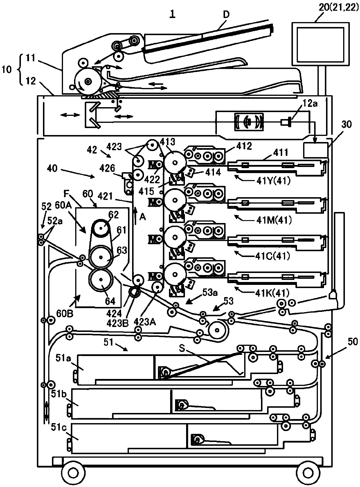
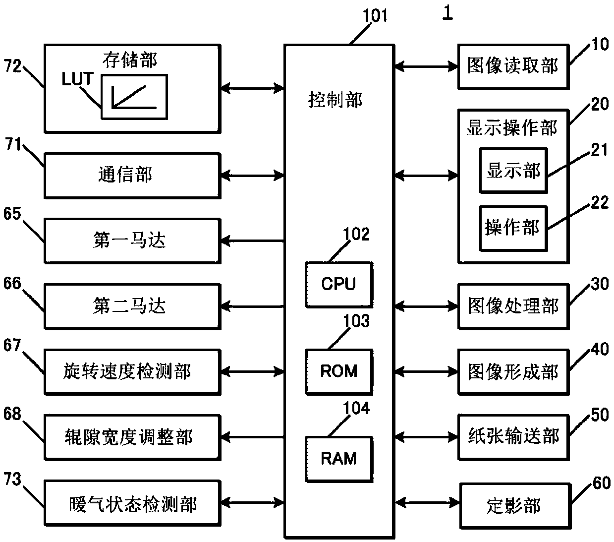
[0035] Hereinafter, this embodiment will be described in detail based on the drawings. figure 1 It is a diagram schematically showing the overall configuration of the image forming apparatus 1 according to the present embodiment. figure 2 It is a diagram showing main parts of the control system of the image forming apparatus 1 according to the present embodiment.

[0036] Such as figure 1 As shown, the image forming apparatus 1 is a color image forming apparatus of an intermediate transfer method using electrophotographic technology. That is, the image forming apparatus 1 primarily transfers the toner images of Y (yellow), M (magenta), C (cyan), and K (black) colors formed on the photosensitive drum 413 to the intermediate transfer belt 421 . The toner images of the four colors are superimposed on the intermediate transfer belt 421 and then secondarily transferred to the paper S sent out from the paper feeding tray units 51 a to 51 c to form an image.

[0037] In addition,...


PUM


Abstract

The present invention provides a fixing device and an image forming apparatus that suppress a fixing failure due to a change in nip width. The fixing device fixes a toner image to a sheet passing through a fixing nip, and is provided with: a first fixing part to which a first driving force is transmitted and which rotates; a second fixing portion that forms a fixing nip with the first fixing portion and that is driven to rotate by rotation of the first fixing portion; a nip width adjustment unit capable of adjusting the nip width of the fixing nip; a rotation speed detection unit that detectsthe rotation speed of the second fixing unit; and a control unit that controls the nip width adjustment unit such that the nip width reaches a predetermined reference nip width on the basis of the detection result of the rotational speed detection unit.

Description

technical field [0001] The present invention relates to a fixing device and an image forming device. Background technique [0002] In general, an image forming apparatus (printer, copier, facsimile, etc.) using electrophotographic technology forms an electrostatic latent image by irradiating (exposing) a charged photosensitive drum (image carrier) with laser light based on image data. Then, by supplying toner from a developing device to the photosensitive drum on which the electrostatic latent image has been formed, the electrostatic latent image is visualized to form a toner image. Then, after the toner image is directly or indirectly transferred to the paper, it is fixed by heating and pressurizing in the fixing nip to form the toner image on the paper. [0003] In an image forming apparatus, various kinds of media are used. Examples of various types of media include media with different basis weights, media with coating on the surface, media without coating, media with ...

Claims


Application Information

Patent Timeline
Patent Type & Authority Applications(China)
IPC IPC(8): G03G15/20
CPCG03G15/2064G03G15/2053G03G15/553
Inventor 泉宫贤二白熊拓美小仓圭吾峰英纪儿玉裕胜
Owner KONICA MINOLTA INC
Features
  • R&D
  • Intellectual Property
  • Life Sciences
  • Materials
  • Tech Scout
  • Unparalleled Data Quality
  • Higher Quality Content
  • 60% Fewer Hallucinations
Learn More