Object arrangement method and device and storage medium
A technology of objects and sorting boxes, applied in the field of data processing, can solve problems such as waste of sorting space, achieve the effect of improving space utilization and solving waste of sorting space
- Summary
- Abstract
- Description
- Claims
- Application Information
AI Technical Summary
Problems solved by technology
Method used
Image

Examples
Embodiment 1
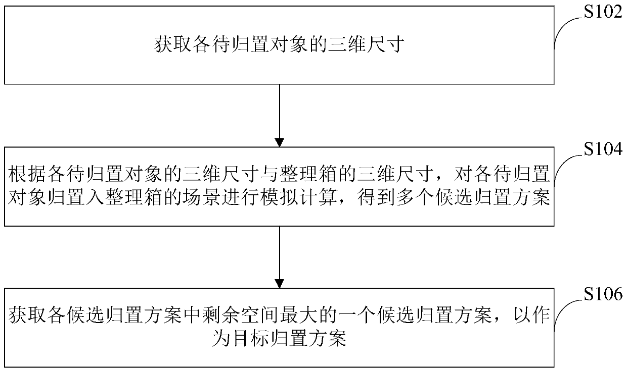
[0040] An embodiment of the present invention provides a method for organizing objects. Please refer to figure 1 , the method includes the following steps:
[0041] S102. Acquire the three-dimensional size of each object to be placed.
[0042] Hereinafter, for the convenience of description, the three-dimensional dimensions involved in the embodiment of the present invention are defined as: x*y*z. That is, the three-dimensional size is characterized by the numerical values on the x-axis, y-axis and z-axis in the three-dimensional space coordinate system.
[0043] Among them, taking the three-dimensional coordinate system where the sorting box is located as the benchmark, the x-axis is used to indicate the length of the sorting box in the three-dimensional coordinate system, the y-axis is used to indicate the width of the sorting box in the three-dimensional coordinate system, and the z-axis is used to indicate the width of the sorting box in the three-dimensional coordinat...
PUM
 Abstract
Description
Claims
Application Information