Double-split transformer wire outlet structure

A dual-split transformer, low-voltage outlet technology, applied in the direction of transformer/inductor coil/winding/connection, transformer/inductor cooling, electrical component structure association, etc. It can easily ensure the direct resistance balance, reduce the width of the fuel tank, and reduce the number of supports.

Inactive Publication Date: 2019-05-17
特变电工山东沈变电气设备有限公司
View PDF10 Cites 2 Cited by
  • Summary
  • Abstract
  • Description
  • Claims
  • Application Information

AI Technical Summary

Problems solved by technology

According to the original plan, the two low-voltage lead wires are arranged on the same side, resulting in an increase in the width of the device body, and it is difficult to support the two outgoing wires. In order to meet the installation and operation requirements of the two low-voltage bushings, a raised seat needs to be installed
The low-voltage lead wire method of the original plan led to an increase in the width of the fuel tank, an increase in oil consumption, waste of copper bars, complicated low-voltage lead-out methods, low production efficiency, difficult installation, and high product costs.

Method used


Image

  • Double-split transformer wire outlet structure
  • Double-split transformer wire outlet structure
  • Double-split transformer wire outlet structure

Examples


Embodiment Construction

[0026] In order to make the object, technical solution and advantages of the present invention clearer, the present invention will be described in detail below in conjunction with the accompanying drawings and specific embodiments.

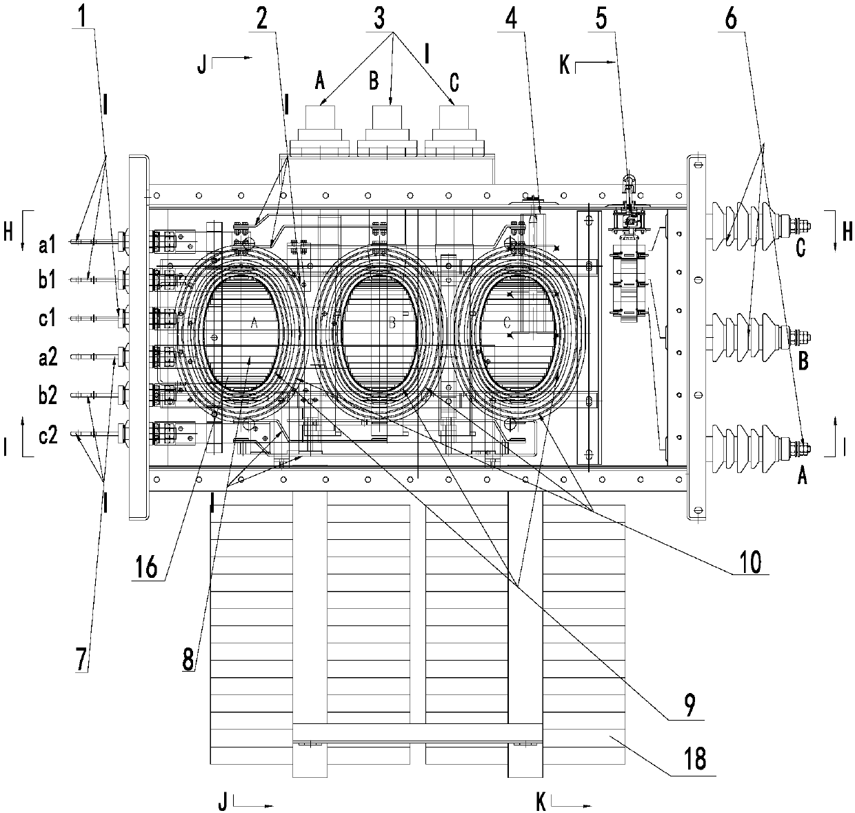
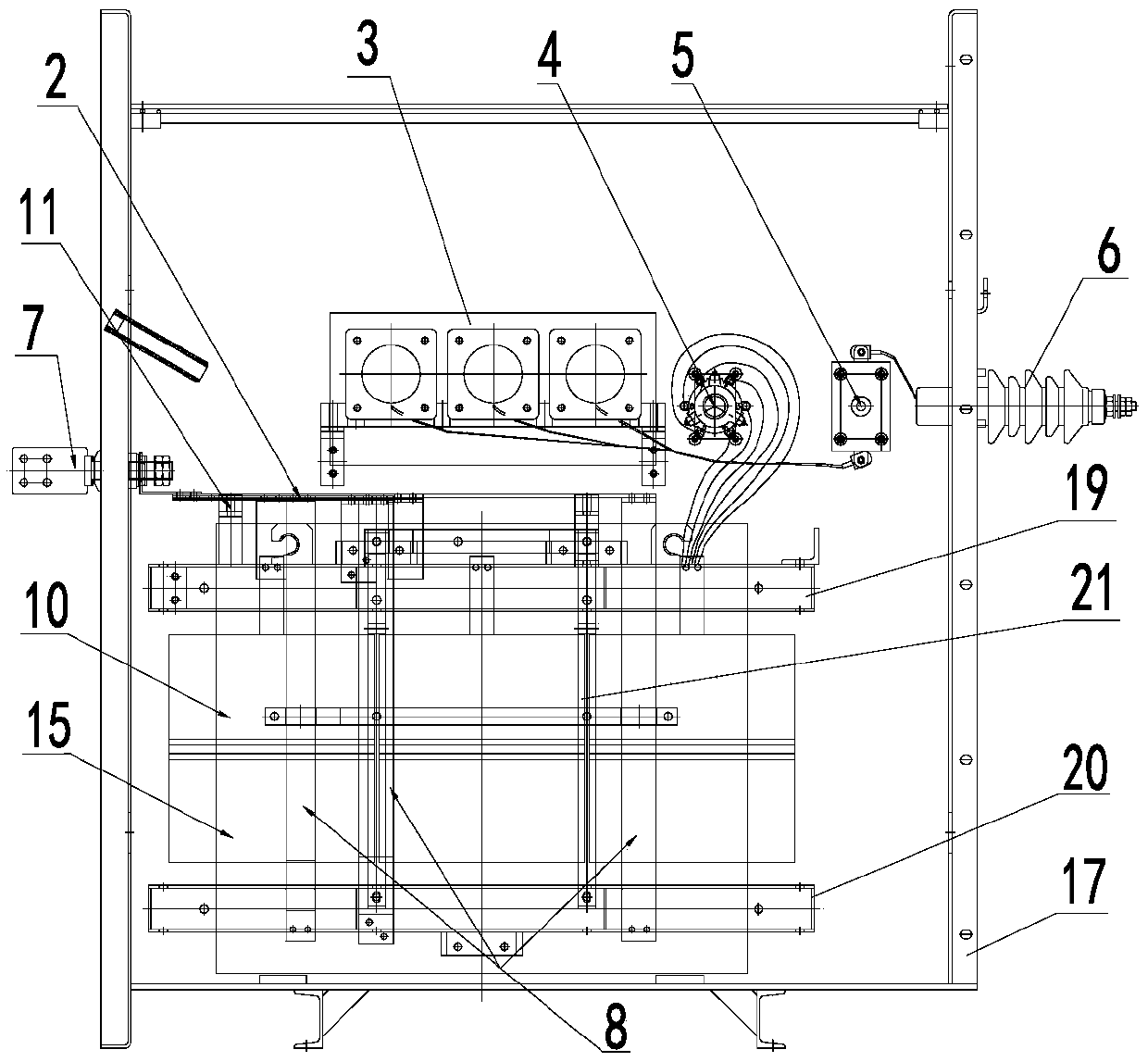
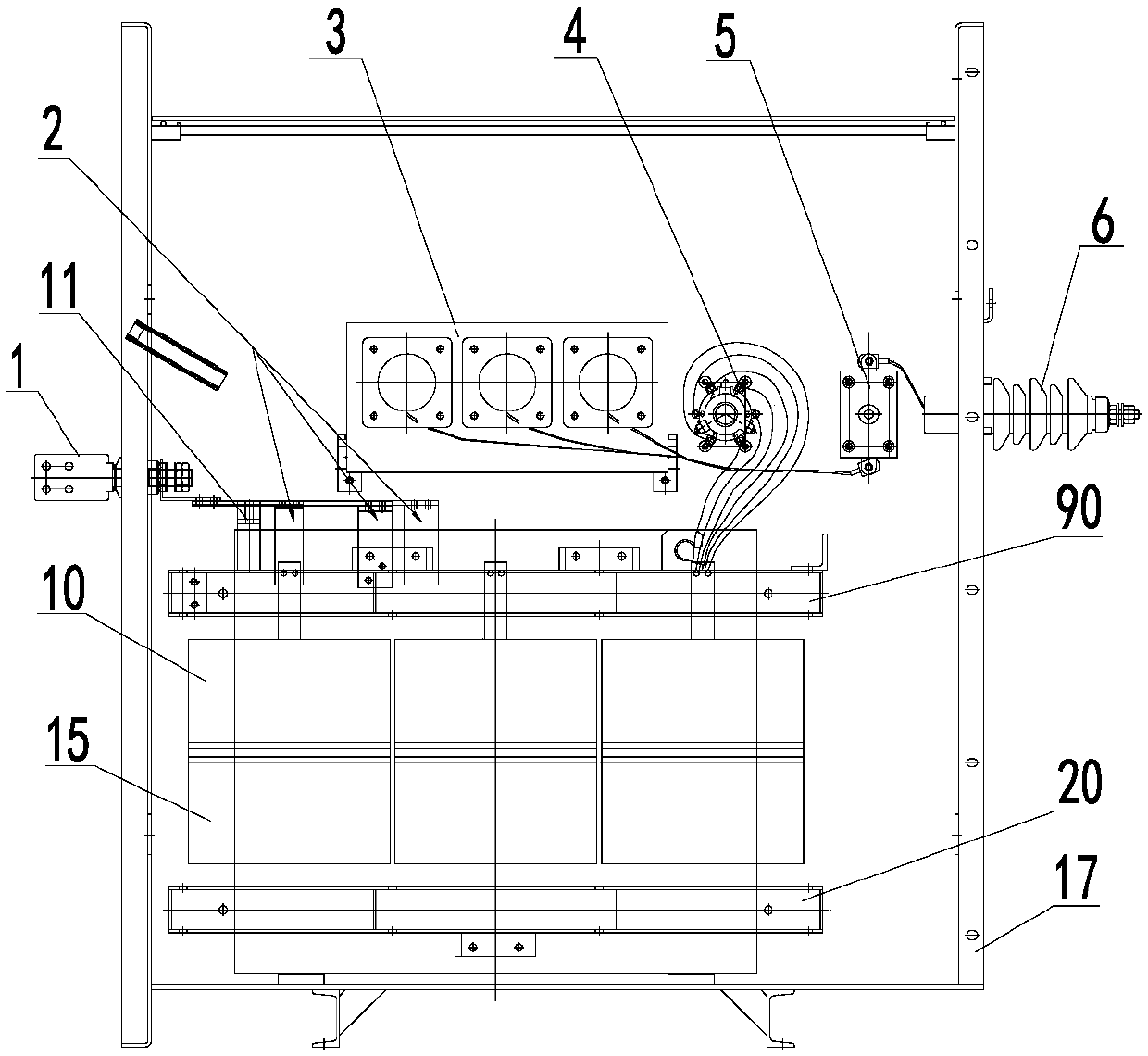
[0027] Such as Figure 1-5 As shown, a double-split transformer outlet structure provided by the present invention includes a three-phase three-column iron core 16 fixed between the upper clamp 19 and the lower clamp 20 and three-phase three-column iron cores 3 wound on the three-phase three-column core 3 respectively. A, B, C three-phase coils, three-phase three-column iron core 3 are arranged in the transformer oil tank 17 . Each phase coil includes an upper low-voltage coil 9, a lower low-voltage coil 14, an upper high-voltage coil 10, and a lower high-voltage coil 15. The upper low-voltage coil 9 and the upper high-voltage coil 10 are concentrically arranged on the upper half of the three-phase three-column iron core 3. The upper high-voltage ...


PUM


Abstract

The invention relates to the technical field of new energy power generation, in particular to a double-split transformer wire outlet structure. The double-split transformer wire outlet structure comprises three phases of three-column iron cores, and A, B and C three phases of coils which are wound around the three phases of three-column iron cores respectively; each phase of the coils comprises anupper part low-voltage coil, a lower part low-voltage coil, an upper part high-voltage coil and a lower part high-voltage coil; the upper part low-voltage coil and the upper part high-voltage coil are concentrically arranged on the upper half parts of the three phases of three-column iron cores, and the lower part low-voltage coil and the lower part high-voltage coil are concentrically arranged on the lower half parts of the three phases of three-column iron cores; the upper part low-voltage coil is connected with a first path of low-voltage sleeve through a first path of low-voltage outgoingline located on one side of the device body, and the lower part low-voltage coil is connected with a second path of low-voltage sleeve through a second path of low-voltage outgoing line located on the other side of the device body; the upper part high-voltage coil is connected with the lower part high-voltage coil in parallel, and a tapping lead is connected with a tapping switch. According to the double-split transformer wire outlet structure, the supporting number of low-pressure wood clamping pieces is reduced, the width of an oil tank is reduced, and the use amount of the transformer oilis reduced.

Description

technical field [0001] The invention relates to the technical field of new energy power generation, in particular to a double-split transformer outlet structure. Background technique [0002] The original photovoltaic power generation double-split transformer high-voltage outgoing line is arranged along the length of the body, and after the lead wire is drawn out, it is connected to a high-voltage fuse, a load switch, and then to a high-voltage bushing. The two low-voltage outlets are arranged on the other side of the body, one of which is led out in the length direction of the upper coil and then led to the low-voltage bushing on the side of the fuel tank; the other low-voltage lead is led out from the lower part of the low-voltage coil, led to the middle of the body, and then vertically connected to the top of the body, and then connect the bushing. According to the original plan, the two low-voltage lead wires are arranged on the same side, resulting in an increase in th...

Claims


Application Information

Patent Timeline
Patent Type & Authority Applications(China)
IPC IPC(8): H01F27/30H01F27/40H01F27/14H01F27/29
Inventor 王乾薛永健韩红军姬立新周朋庞宪国武文钊
Owner 特变电工山东沈变电气设备有限公司
Why Eureka
Try Eureka