
Nursing bed with defecation device

A technology for nursing beds and toilets, which is applied to hospital beds, medical science, hospital equipment, etc., can solve the problems of complex structure, lack of cleanliness and comfort for patients and elderly people who cannot take care of themselves, and easy to wet and dirty mattresses, etc. To achieve the effect of simple linkage structure, flexible, smooth and reliable operation

Pending Publication Date: 2019-05-21
NINGBO TIANMING ELECTRONICS
View PDF1 Cites 5 Cited by
  • Summary
  • Abstract
  • Description
  • Claims
  • Application Information

AI Technical Summary

Problems solved by technology

[0003] But the nursing bed with defecation device of prior art, the toilet bucket is generally positioned at the below of the urinal hole of mattress or title cushion, and patient and the old man who can't take care of oneself urinates and easily gets wet and dirty mattress, makes patient and the old man who can't take care of oneself lack of Cleanliness and comfort
In addition, its toilet lifting or lowering device and the toilet plug lifting or disengaging device for sealing the toilet hole are more and more inclined to complicate its structure. If any, the toilet bucket needs to be slid to the bottom of the toilet hole first, and then use the driving lever Wait for the mechanism to push the toilet up

Method used


Image

  • Nursing bed with defecation device
  • Nursing bed with defecation device
  • Nursing bed with defecation device

Examples

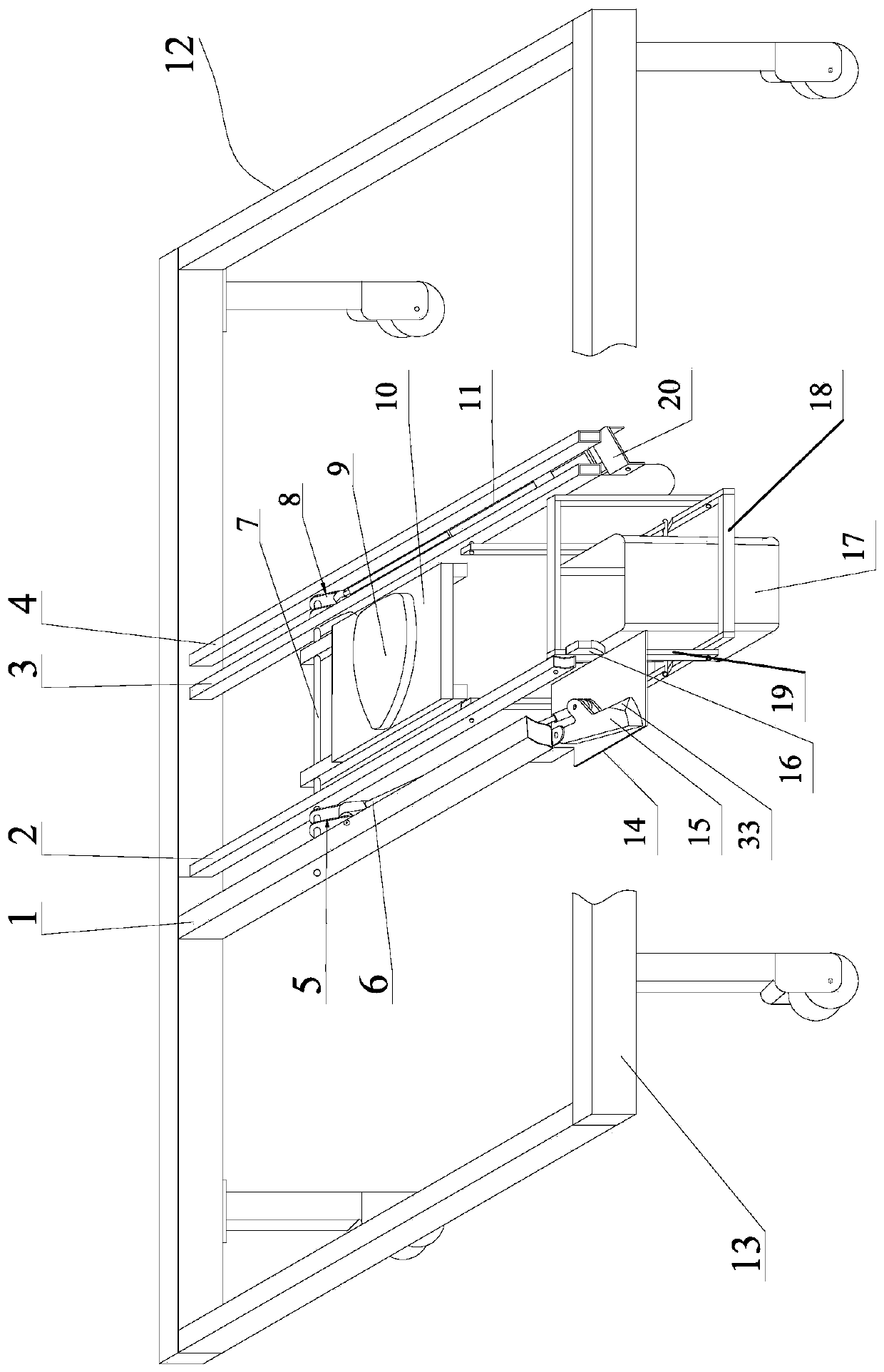
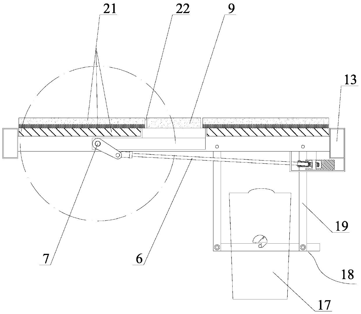
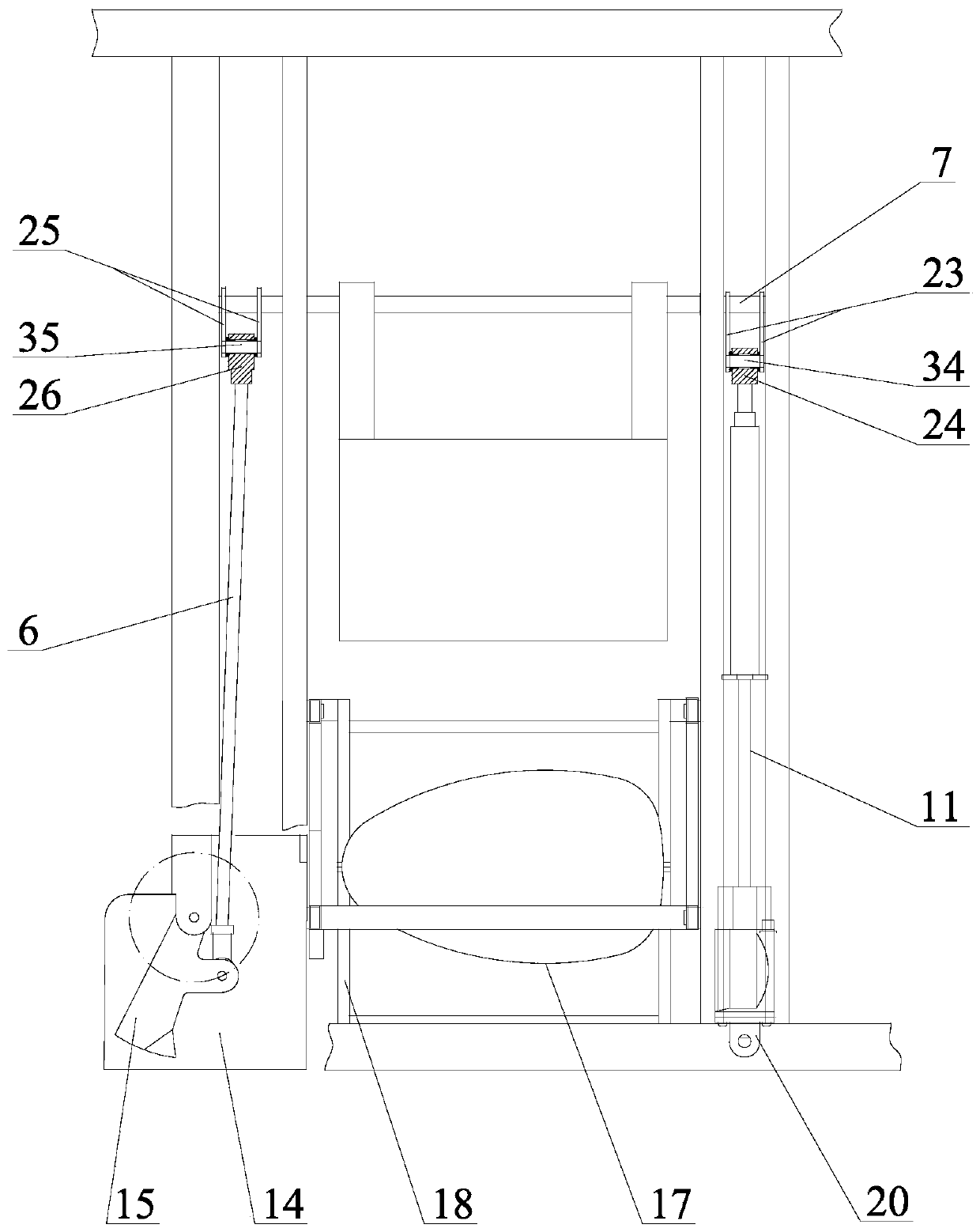

Embodiment Construction

[0025] The specific embodiments of the present invention will be further described below in conjunction with the accompanying drawings. What needs to be declared here is that the descriptions of these specific implementations are used to help understand the present invention, but are not intended to limit the present invention. In addition, the technical features involved in the various specific embodiments of the present invention described below may be combined with each other as long as they do not constitute conflicts with each other.

[0026] like figure 1 , figure 2 , image 3 , Figure 4 , Figure 5 , Image 6 shown

[0027] The nursing bed with defecation device of the present invention comprises a bed frame 12 provided with at least two longitudinal beams 13 and multiple beams, a mattress 21 placed above the first beam 3 and the second beam 2 among the multiple beams, the The mattress 21 is provided with a toilet hole 22 . The mattress can adopt a structure i...


PUM


Abstract

The invention discloses a nursing bed with a defecation device, which comprises a bed frame and a bed mattress arranged on a first beam and a second beam. The mattress is provided with a defecation hole, the bed also comprises a commode holder frame with an inside commode and a plurality of swing rods, wherein the upper end of the frame is hinged on the first beam and the second beam; one end of an electric push rod is fixed on a bed frame, other end is hinged with one end of a first joint, the other end of the first joint is fixed at one end of a rotating shaft of a defecation hole plug frameprovided with a defecation hole plug; the other end of the rotating shaft is fixedly connected with one end of a second joint, the other end of the second joint is hinged with one end of a connectingrod, the other end of the connecting rod is hinged with a middle lug of a drive block of the commode holder frame, one end of the drive block of the commode holder frame is hinged with the bed frame,the other end of the drive block of the commode holder frame is provided with push blocks arranged on a swing bar to make the top of the commode pass through the defecation hole and contact the buttock of a defecator. The bed is simple in structure and the cleaning feeling and comfort feeling are strong.

Description

Technical field [0001] The present invention relates to the technical field of medical care equipment, specifically a care bed with a defecation device. Background technique [0002] The nursing beds of the existing technology have relatively complete functions in enabling patients to turn over, lie down, sit, and have armrests to eat. There are also nursing beds that enable patients in hospital beds and elderly people who cannot take care of themselves to defecate without getting out of bed. Many literature disclosures. [0003] However, in the nursing beds with defecation devices in the prior art, the toilet bowl is generally located under the stool hole of the mattress or cushion. Patients and the elderly who cannot take care of themselves can easily wet and dirty the mattress with their urine and urine, which makes the patients and the elderly who cannot take care of themselves lack of resources. A sense of cleanliness and comfort. In addition, the structure of the toi...

Claims


Application Information

Patent Timeline
IPC IPC(8): A61G7/02A61G7/015A61G7/05
Inventor 俞益庭张旭辉
Owner NINGBO TIANMING ELECTRONICS
Learn More