Turning-over clamp

A technology of overturning fixtures and rotating rods, applied in the directions of clamping, manufacturing tools, supports, etc., can solve problems such as increasing labor intensity, reducing production efficiency, and processing errors

Inactive Publication Date: 2019-05-21
ANHUI POLYTECHNIC UNIV MECHANICAL & ELECTRICAL COLLEGE
View PDF8 Cites 5 Cited by
  • Summary
  • Abstract
  • Description
  • Claims
  • Application Information

AI Technical Summary

Problems solved by technology

[0003] With regard to the above-mentioned prior art, the purpose of the present invention is to overcome the multi-face machining of the workpiece to be processed in the prior art, which generally requires multiple clamping, which not only causes machining errors, but also increases labor intensity and reduces production efficiency. At the same time, the general The clamping fixture often realizes multi-faceted processing through the workbench, and it is impossible to conveniently process the workpiece itself, thus providing a flipping fixture that can complete multiple multi-faceted processing operations with only one manual clamping

Method used


Image

  • Turning-over clamp
  • Turning-over clamp

Examples


Embodiment Construction

[0029] Specific embodiments of the present invention will be described in detail below in conjunction with the accompanying drawings. It should be understood that the specific embodiments described here are only used to illustrate and explain the present invention, and are not intended to limit the present invention.

[0030] In the present invention, unless otherwise specified, the used orientation words such as "upper, lower, vertical, horizontal" refer to the positional relationship in actual use.

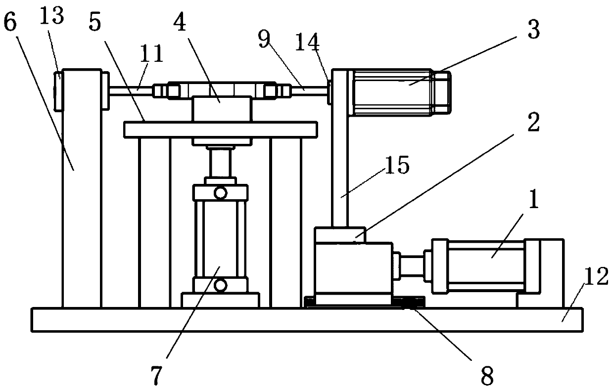
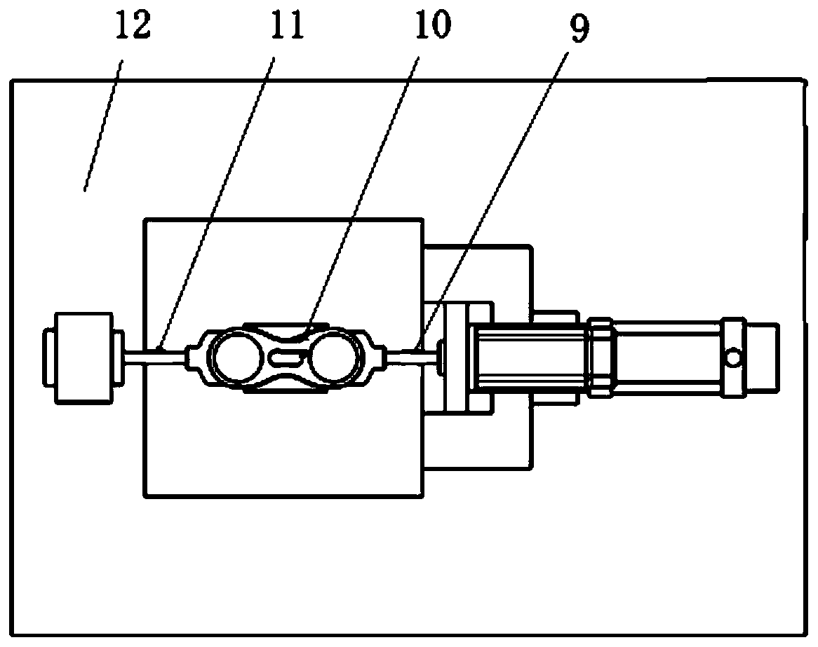
[0031] The invention provides a flipping fixture, wherein, such as figure 1 and figure 2 As shown, the flip fixture includes a first clamping unit, a workpiece placement unit, a second clamping unit and a drive unit arranged in sequence; wherein,

[0032] The first clamping unit at least includes a vertically arranged first support platform 6, a first sliding block 13 that is vertically slidably arranged on the first support platform 6, and a first sliding block 13 that is ro...


PUM


Abstract

The invention discloses a turning-over clamp. The turning-over clamp comprises a first clamping unit, a workpiece storing unit, a second clamping unit and a drive unit which are arranged sequentially.The first clamping unit at least comprises a first supporting table (6), a first sliding block (13) capable of sliding in the vertical direction, and a first rotating rod (11) arranged in a self-rotating manner. The workpiece storing unit at least comprises a first hydraulic cylinder (7), and a workpiece putting table (4) arranged on the first hydraulic cylinder. The second clamping unit at leastcomprises a sliding rail (8), a second supporting table (2) capable of sliding on the sliding rail, a second sliding block (14) arranged on the second supporting table in a sliding manner in the vertical direction, and a second rotating rod (9) arranged on the second sliding block in a self-rotating manner. The first rotating rod and the second rotating rod are connected with clamping parts correspondingly. The clamping parts are arranged above the workpiece putting table. According to the turning-over clamp, the effect of completing multi-time and multi-face machining operation only by one-time manual clamping can be achieved.

Description

technical field [0001] The invention relates to the field of processing auxiliary devices, in particular, to a turning fixture. Background technique [0002] At present, in the machinery manufacturing industry, when processing different surfaces, the workpiece often requires secondary clamping, and multiple processing requires multiple clamping. This processing method will not only cause processing errors, but also increase labor intensity and reduce productivity. Although some fixtures have a certain flipping effect, the workpiece is often multi-faceted processed through the flipping of the workbench, which makes it impossible to conveniently process the workpiece itself. Contents of the invention [0003] With regard to the above-mentioned prior art, the purpose of the present invention is to overcome the multi-face machining of the workpiece to be processed in the prior art, which generally requires multiple clamping, which not only causes machining errors, but also in...

Claims


Application Information

Patent Timeline
IPC IPC(8): B23Q3/08B23Q1/25
Inventor 张继东时浩东
Owner ANHUI POLYTECHNIC UNIV MECHANICAL & ELECTRICAL COLLEGE
Why Eureka
Try Eureka