Positioning structure with precise position capture function

A technology for positioning structure and function, applied in the field of electronics, can solve the problems of complex manufacturing process, complex structure, and unsuitable for large-area use.

Pending Publication Date: 2019-05-21
赵浩东
View PDF2 Cites 0 Cited by
  • Summary
  • Abstract
  • Description
  • Claims
  • Application Information

AI Technical Summary

Problems solved by technology

However, there are still disadvantages such as complex production process, cumbersome procedure

Method used


Image

  • Positioning structure with precise position capture function
  • Positioning structure with precise position capture function
  • Positioning structure with precise position capture function

Examples


Embodiment Construction

[0045] In order to make the object, technical solution and advantages of the present invention clearer, the present invention will be further described in detail below in conjunction with the accompanying drawings and embodiments. It should be understood that the specific embodiments described here are only used to explain the present invention, not to limit the present invention.

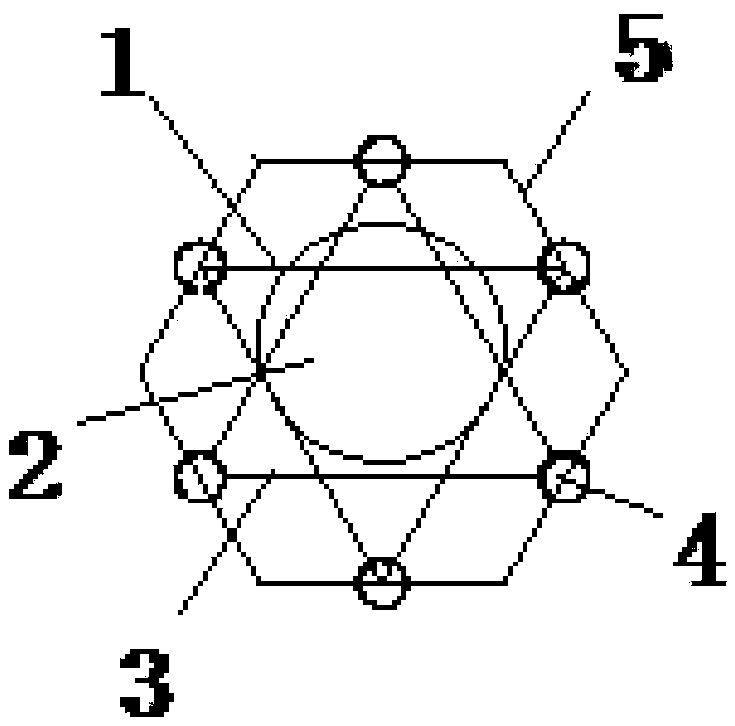
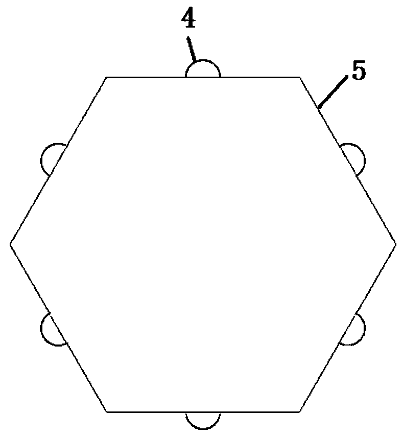
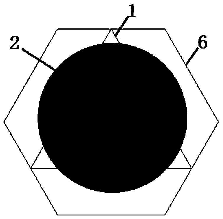
[0046] see Figure 1-4As shown, the present invention provides a positioning structure with a precise position capture function, the structure includes a first conductive line 1, a space isolation layer 2 and a second conductive line 3, the end points of the first conductive line 1 and the second conductive line 3 The first conductive wire 1 and the second conductive wire 3 are spaced apart by the space isolation layer 2, and the first conductive wire 1 and the second conductive wire 3 contact and conduct with each other after being squeezed. The first conductive wire 1 and the second conductive w...


PUM


Abstract

The invention discloses a positioning structure with the precise position capture function. The positioning structure comprises a first conductive line, a space isolation layer and a second conductiveline, the end points of the first conductive line and the second conductive line are connected with conductive elements respectively, the first conductive line and the second conductive line are isolated through the space isolation layer in a space mode, and the first conductive line and the second conductive line makes contact with each other and communicates with each other after being squeezed. The positioning structure is simple in structure, high in positioning accuracy, convenient to combine and use by a large area, low in production cost, high in use effect, high in adaptability, and convenient to widely popularize, the positioning structure is composed of multiple combinations, and the modular connection network using is achieved.

Description

technical field [0001] The invention belongs to the field of electronic technology, in particular to a positioning structure. Background technique [0002] Tactile sensors, that is, bionic skin, play an important role in human-computer interaction tasks. The role of the bionic skin of the robot is to simulate the human tactile nervous system to sense the point of contact with the external environment and the magnitude of the contact force, thereby providing information for robot path planning and contact force control. Bionic skin is the product of the combination of materials and electronic technology. With the development of computer technology, it will become more and more common for bionic skin to be applied to various robots in the future. However, most of the existing robotic tactile sensors have disadvantages such as complex matrix structure, customization according to size, high production cost, high maintenance cost, and not suitable for large-area use. [0003] A...

Claims


Application Information

Patent Timeline
IPC IPC(8): B25J19/02
Inventor 赵浩东
Owner 赵浩东
Why Eureka
Try Eureka