Driving positioning device and driving positioning method based on radio frequency identification technology

A radio frequency identification technology, radio frequency identification technology, applied in the field of driving positioning devices, can solve the problems of high cost, data deviation, heavy maintenance workload, etc., and achieve the effect of reliable operation, avoiding wear and error, and simple equipment installation

Inactive Publication Date: 2013-01-30
BAOSHAN IRON & STEEL CO LTD
View PDF6 Cites 13 Cited by
  • Summary
  • Abstract
  • Description
  • Claims
  • Application Information

AI Technical Summary

Problems solved by technology

The existing driving positioning method using laser ranging sensors usually installs a laser ranging sensor at an appropriate position at both ends of the driving track, and installs a double-sided reflector on the driving body, and extracts the laser sensor measurement through a data acquisition card. Data and proofreading, the position parameters of the vehicle can be obtained; this method needs to be equipped with long-distance high-precision laser sensors and corresponding data acquisition cards, the cost is relatively expensive, and it is not suitable for harsh conditions such as smoke and dust in the on-site environment Use under
Another type of existing positioning method for driving and cranes based on rotary encoders is usually to install traveling wheels on the shaft of the rotary encoder, and the traveling wheels are pressed against the driving track by an elastic mechanism. Move and drive the rotary encoder to rotate to record the driving position data information; this method uses a mechanical pressing structure, so it is easy to cause data deviation due to wear and slipping, and the maintenance workload is relatively large

Method used


Image

  • Driving positioning device and driving positioning method based on radio frequency identification technology
  • Driving positioning device and driving positioning method based on radio frequency identification technology
  • Driving positioning device and driving positioning method based on radio frequency identification technology

Examples


Embodiment 1

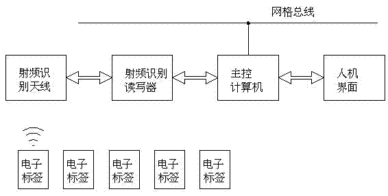
[0024] RFID, or Radio Frequency Identification, is a technology that uses radio frequency signals to achieve contactless information transmission through spatial coupling and achieves identification purposes through the transmitted information. Such as figure 1 As shown, the most basic radio frequency identification system consists of four parts: electronic tag, radio frequency identification reader, radio frequency identification antenna and main control computer. The internal chip of the electronic tag can store certain data information. It uses the radio wave emitted by the radio frequency identification antenna as the energy source. The data stored in the internal is transmitted, received by the radio frequency identification antenna, and processed and controlled by the main control computer. After the main control computer is connected with the man-machine interface, it is convenient for observation and operation.

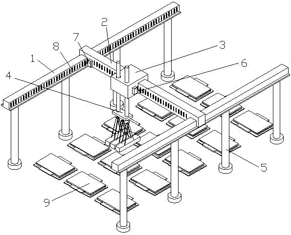
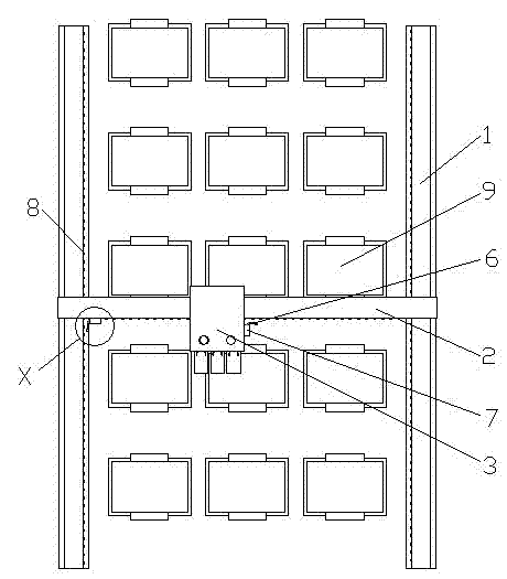
[0025] Such as figure 2 , 3 , shown in 4, a kind...


PUM


Abstract

The invention relates to the field of driving control, in particular to a driving positioning device and a driving positioning method. The driving positioning device based on radio frequency identification technology comprises a radio frequency identification antenna, radio frequency identification reader and writer, an electronic tag and a master control computer. The radio frequency identification reader and writer are fixedly installed on a carriage and a trolley respectively. The master control computer is connected with the radio frequency identification antenna through the radio frequency identification reader and writer. The electronic tag is installed on a driving track and the carriage. The driving positioning method based on the radio frequency identification technology includes: defining a space coordinates system, setting the electronic tag at the position matching with the coordinates system, writing position data information in the electronic tag in advance, and allowing the radio frequency identification antenna to read the electronic tag to achieve automatic driving positioning. The driving positioning method is a non-contact positioning technology. Wear and errors caused by mechanical devices are avoided. By writing relevant information in the electronic tag, the positioning function can be realized, and current material stacking and driving status information can also be reflected.

Description

technical field [0001] The invention relates to the field of driving control, in particular to a driving positioning device and method. Background technique [0002] In enterprise warehouses, ports, freight yards and other places, a large number of machinery such as cranes, overhead cranes or bridge cranes are used for handling operations. The loading and unloading of materials and goods, as well as the transfer between stacks, require position recognition and control. At present, there are many positioning methods for cranes and overhead cranes, such as the manual identification method, which assists the crane operator to judge the position of the spreader by making character marks on the wall or beam in the direction of the running direction of the crane. The accuracy of this method is not high. It also requires the judgment and adjustment of the driving operator. In addition, the labor intensity of the operator is relatively high, and it is prone to misjudgment, which wil...

Claims


Application Information

Patent Timeline
Patent Type & Authority Applications(China)
IPC IPC(8): G06K17/00
Inventor 乔俊良吴瑞珉王怡然潘胜波杨赛丹金成国
Owner BAOSHAN IRON & STEEL CO LTD
Why Eureka
Try Eureka