Head portion folding device for plastic bags

A folding device and plastic bag technology, applied in packaging, paper product packaging, transportation and packaging, etc., can solve the problems of large machine volume, affecting folding speed, complex structure, etc., to achieve the effect of compact overall structure and improve production efficiency

Inactive Publication Date: 2019-05-21
王秀来
View PDF1 Cites 1 Cited by
  • Summary
  • Abstract
  • Description
  • Claims
  • Application Information

AI Technical Summary

Problems solved by technology

This causes many problems such as the whole set of equipment is bulky, complex in structure and high in manufacturing cost.
Another problem is: the two handles 90 of the plastic bag must be built together when being folded, that is, a handle 90 is pressed on the other handle 90 to form a Figure 5 state shown
But have caused more unfavorable problem thus: the one is that the amplitude of handle folding push plate motion is bigger, makes the volume of machine bigger; If there is a pallet spring, the front side of the handle folding pallet is hinged on the handle folding bracket. After the two handle folding push plates are pushed out to the middle, the rear side of the folding pallet can be The predetermined folding line position of the plastic bag is clamped on the rear side of the two handle folding push plates. When the flipping pallet is turned over together with the two handle folding push plates, a neat line will be formed at the clamped position. folding line
Although the U-shaped push-and-fold plate of Comparative Document 2 reduces the problem of the extent of pushing and folding the push plate to both sides, and can also put the two handles of the plastic bag together, it also brings the following problems: first, When the bag passing clamp (i.e. the manipulator) of the plastic bag folding machine passes under the trapezoidal platen and puts the plastic bag to the folding working position, the first step of the folding work is that the trapezoidal platen mechanism moves downward and presses on the folding flap. , and the downward pressure of the trapezoidal platen hinders the return of the bag-passing manipulator, so the trapezoidal platen will start to move down after the bag-passing manipulator puts down the plastic bag and returns. This waiting will seriously affect the folding speed and reduce work efficiency. The current bag folding machines are all high-speed, and the bag folding machines can only cooperate by reducing the speed; second, during the folding process of the folding flap, the two handles of the plastic bag are clipped by the pressure bag hook. It lives on the folding flap, and the release time of the hook of the pressure bag is difficult to adjust. If it is released too late, it will hinder the folding of the folding flap, and even damage the plastic bag. If it is released too early, it has been put together The two handles are easy to sag or fall apart; and the size and type of the plastic bags are different, the thickness is different, the material and elasticity of the plastic bags are also different, and the inertial force is different under the centrifugal force of the folding flap. Yes, so the adjustment of the pressure bag hook is frequent and difficult to adjust; third, when the pressure bag hook clamps the front of the plastic bag on the folding flap and then folds back together with the folding flap At the time, the said pressure bag crotch can no longer fold the rear side of the flap to form a crease on the first folding line position of the plastic bag. Therefore, even if it is folded over, it is easy to lift because of the greater elasticity of the plastic bag. Will seriously affect the reliability and stability of folding

Method used


Image

  • Head portion folding device for plastic bags
  • Head portion folding device for plastic bags
  • Head portion folding device for plastic bags

Examples


Embodiment Construction

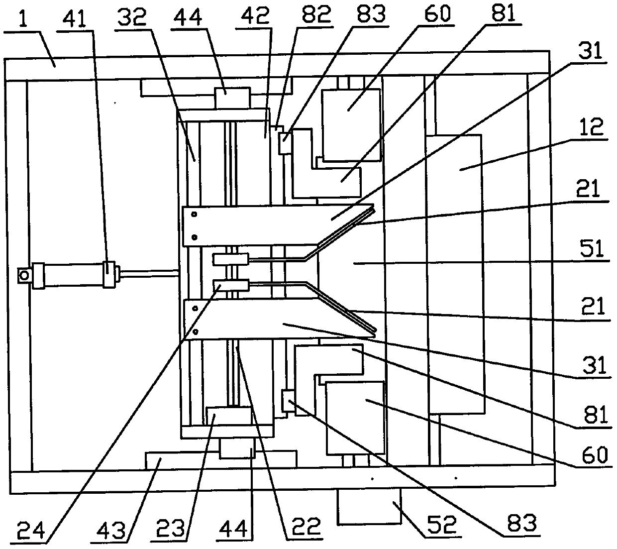
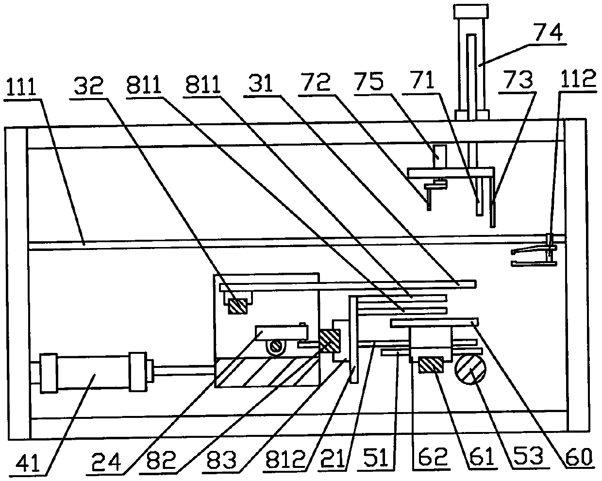
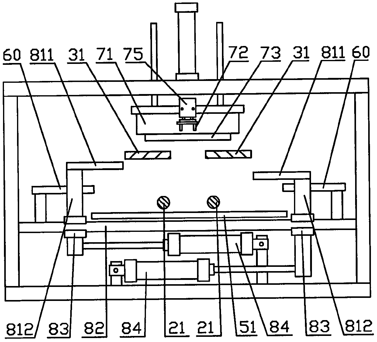
[0024] Such as Figure 1 to Figure 10 Shown, the left side of accompanying drawing is exactly the front described in the present invention, and the right side of accompanying drawing is exactly the described back of the present invention; The top of accompanying drawing is exactly the right side described in the present invention, and the following of accompanying drawing is exactly the left side described in the present invention . In order to fully disclose the technical solutions of the present invention, the present invention will be specifically described below through examples.

[0025] Examples such as figure 1 , figure 2 , image 3 Shown: install a tray rack slide rail 43 front and rear respectively on both sides of the front part of the frame 1, set a tray rack 42, install a slider 44 respectively on the left and right sides of the tray rack 42, make the tray rack 42 pass through the slider 44 is slidably installed on two pallet frame slide rails 43, and a cylin...


PUM


Abstract

The invention discloses a head portion folding device for plastic bags. The head portion folding device mainly comprises a rack, a plastic bag conveying device, a pressing rod mechanism, a lifting handle upturning tray mechanism, a tray longitudinal motion device, a folding support plate mechanism, a folding push plate mechanism and a plastic bag compressing device and is characterized in that anL-shaped push plate mechanism and a push plate driving mechanism are further arranged between two lifting handle folding push plates of the folding push plate mechanism. The head portion folding device for the plastic bags has the beneficial effects that the moving amplitude of the lifting handle folding push plates can be reduced to a large extent, and the whole head portion folding device is made to be compact in structure; two lifting handles of the plastic bags can be folded together in a mutually-intersected manner, and banding is performed firmly; and the pushing folding function of thelifting handle folding push plates in the prior art is converted into the function of clamping the plastic bags, and the folding reliability of a folding support plate is improved.

Description

technical field [0001] The invention relates to a head folding device of a plastic bag. Background technique [0002] The plastic bag involved in the present invention refers to a convenience bag with two handles, also known as a vest bag and a shopping bag, which are generally automatically processed and produced by a bag making machine, and the bag making machine will output a stack or Two stacks of plastic bags, usually dozens of plastic bags. In order to facilitate storage, transportation, sale, and use, these stacked plastic bags generally need to be folded three to four times, and finally folded into long strips, and then bundled or packed into packaging bags. The shape of the plastic bag and its folding procedure are as follows: Figure 4 with Figure 5 As shown: first, the two handles 90 of the two plastic bags need to be folded in the middle at the position of the handle folding line 91, so that the two handles 90 can be put together and folded into a Figure 5 I...

Claims


Application Information

Patent Timeline
Patent Type & Authority Applications(China)
IPC IPC(8): B65B63/04B65B25/14B65B27/08
Inventor 王秀来
Owner 王秀来
Why Eureka
Try Eureka