
Column foundation cup mouth core formwork anti-floating device and construction method

A column foundation and mandrel technology, which is applied in the field of anti-floating device for the cup mouth mandrel of the column foundation, can solve the problems of inconvenient construction, increased cost, labor and time consuming, etc.

Pending Publication Date: 2019-05-21
CHINA 22MCC GROUP CORP
View PDF1 Cites 0 Cited by
  • Summary
  • Abstract
  • Description
  • Claims
  • Application Information

AI Technical Summary

Problems solved by technology

The cup mouth method is used to facilitate the installation and adjustment of the column. Then, the cup mouth foundation mandrel is subjected to lateral pressure during the concrete pouring process, causing the mandrel to float up, resulting in the elevation of the bottom of the foundation cup mouth. Time-consuming and extremely inconvenient for construction
[0003] Chinese invention patent CN 107524156 A discloses an anti-floating method for the core mold of the cup mouth column foundation. This method is sometimes used in construction, but there is a need to set tie bars, and the tie bars cannot be reused, which increases the cost
Another common method of fixing the mandrel and anti-floating is to use wooden squares to clamp the mandrel. The wooden square is not straight and the strength is not high, and it is easy to cause the wooden square to bend and deform under lateral pressure, which will affect the quality of the cup foundation molding

Method used


Image

  • Column foundation cup mouth core formwork anti-floating device and construction method
  • Column foundation cup mouth core formwork anti-floating device and construction method
  • Column foundation cup mouth core formwork anti-floating device and construction method

Examples


Embodiment Construction

[0027] The present invention will be described in detail below in conjunction with the accompanying drawings and embodiments.

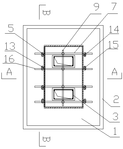
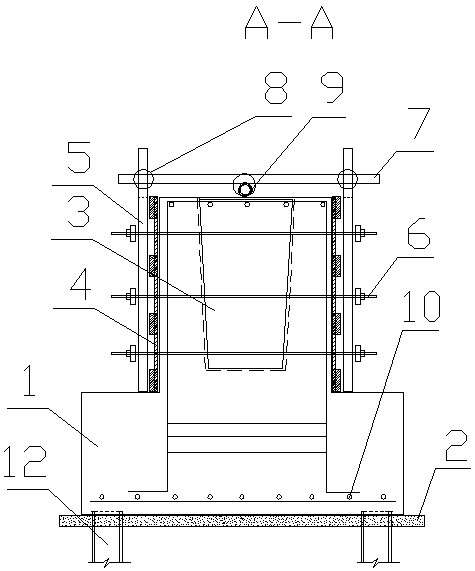
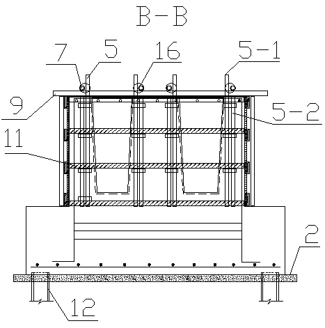
[0028] see figure 1 , figure 2 , image 3 , an anti-floating device for a column foundation cup mouth mandrel, which consists of a column foundation 1, a cushion layer 2, a mandrel 3, a template 4, a template back group 5, a tension screw 6, a cross bar 7, a right-angle fastener 8, Anti-floating rod 9, foundation reinforcement, wooden square keel 11 and pile 12 constitute. Above the pile 12 is a cushion layer 2 , above the cushion layer 2 is a column foundation 1 , and foundation steel bars 10 are laid in the column foundation 1 .

[0029] The upper part of the column foundation 1 is installed with a rectangular formwork 4 with a cross-section, and a mandrel 3 is installed in the formwork 4. In the present embodiment, the mandrel 3 is two pieces, and a wooden square keel 11 is installed in the formwork 4. The two sides of formwork 4 are respectiv...


PUM


Abstract

The invention relates to building construction, in particular to a column foundation cup mouth core formwork anti-floating device and a construction method. The device comprises a column foundation, and a cushion layer and a pile are sequentially arranged under the column foundation. A formwork is mounted at the upper part of the column foundation. A core formwork is arranged in the formwork. Leftfront, left back, right front and right back formwork dorsal bar groups corresponding to four corners of the core formwork are arranged at two sides of the formwork respectively. Each formwork dorsalbar group comprises a first scaffold pipe and a second scaffold pipe which are vertically arranged in parallel. The height of the first scaffold pipe is larger than that of the formwork, a first transverse rod and a second transverse rod are installed between the corresponding first scaffold pipes on the left side and the right side of the formwork respectively, a longitudinal anti-floating rod is installed between the first transverse rod and the second transverse rod, and the anti-floating rod is located above the core formwork and fixedly connected with the core formwork. The elevation canbe flexibly adjusted, fine adjustment is convenient, the anti-floating stress mode is a core formwork top stress mode, and the effect is remarkable compared with the effect that a batten clamps a core formwork to bear shearing force. The anti-floating device is not provided with tie bars, steel is saved, and cost is reduced.

Description

technical field [0001] The invention relates to building construction, in particular to an anti-floating device and a construction method for a cup mouth mandrel of a column foundation. Background technique [0002] As we all know, in the construction industry, various factories are often seen. Except for some light structures that use bolts or embedded parts, more than 90% of the column foundations are in the form of cups, especially in metallurgical industry factories. The cup mouth method is used to facilitate the installation and adjustment of the column. Then, the cup mouth foundation mandrel is subjected to lateral pressure during the concrete pouring process, causing the mandrel to float up, resulting in the elevation of the bottom of the foundation cup mouth. It is labor-intensive and time-consuming, and the construction is extremely inconvenient. [0003] Chinese invention patent CN 107524156 A discloses an anti-floating method for the core mold of the cup mouth co...

Claims


Application Information

Patent Timeline
IPC IPC(8): E02D27/42E02D31/12
Inventor 王代发张春勇
Owner CHINA 22MCC GROUP CORP
Features
  • Generate Ideas
  • Intellectual Property
  • Life Sciences
  • Materials
  • Tech Scout
  • Unparalleled Data Quality
  • Higher Quality Content
  • 60% Fewer Hallucinations
Learn More