
Constant-current water distribution equipment and method

A technology of water distribution and equipment, applied in the direction of mining fluid, earthwork drilling, wellbore/well components, etc., can solve problems such as heavy workload, short stable water injection cycle, and change in water injection volume, so as to improve the qualified rate and have broad application prospects , to achieve the effect of constant flow

Active Publication Date: 2019-05-21
CHINA PETROLEUM & CHEM CORP +1
View PDF7 Cites 0 Cited by
  • Summary
  • Abstract
  • Description
  • Claims
  • Application Information

AI Technical Summary

Problems solved by technology

[0006] The purpose of the present invention is to provide a constant flow water distribution equipment and method and pipe column, which can solve the change of water injection volume caused by pressure fluctuations in the layered water injection process. For major problems, the flow of each water injection layer is stably controlled by installing constant flow water injection valves on the layered water injection strings. The water injection valves of each layer adopt hydraulic control mode. When the water injection volume of a certain layer drops, in order to ensure If the water injection of the well is qualified, the wellhead pressure will be automatically adjusted and increased, and the outlet valve hole will be automatically reduced in other layers affected by the pressure increase, so as to control the water injection volume to remain stable; If it is qualified, the wellhead pressure will be automatically adjusted and reduced. At this time, the remaining layers will be affected by the pressure reduction, and the water outlet valve hole will automatically expand, and the controlled water injection will also remain stable.

Method used


Image

  • Constant-current water distribution equipment and method
  • Constant-current water distribution equipment and method

Examples


Embodiment Construction

[0026] The detailed description and technical content of the present invention are described below with the drawings, but the drawings are only for reference and description, and are not used to limit the present invention.

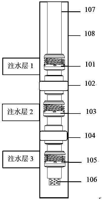
[0027] according to figure 1 , a constant flow water distribution equipment, including an inner center pipe 4, a swimming valve 5, a water outlet valve 8, a constant flow fixed valve 9, a throttle valve plate 10, a rotary joint 11, and the swimming valve 5 is set in the inner center pipe 4 Externally, the inner wall of the floating valve is provided with an inner ring platform, and the inner wall of the inner ring platform is connected with the outer wall of the inner central pipe in a sealed and sliding manner. The upper ring cavity is formed above the inner ring platform, and the lower ring cavity is formed below the inner ring platform. The central pipe is provided with a radial pressure transmission hole connected to the upper ring cavity, and a thrus...


PUM


Abstract

The invention discloses constant-flow water distribution equipment and method, and a pipe column. The equipment comprises an inner central tube, a traveling valve, a water outlet valve, a constant-flow fixed valve, a throttling valve plate and a rotary joint. The traveling valve is sleeved outside the inner central pipe; an inner ring table is arranged on the inner wall of the traveling valve; theinner wall of the inner ring table is in sealed sliding connection with the outer wall of the inner central pipe; an upper annular cavity is formed in the upper portion of the inner annular table; alower ring cavity is formed in the lower portion of the inner ring table; the inner central pipe is provided with a radial pressure transmission hole communicating the upper annular cavity; a thrust spring is arranged in the lower ring cavity in the traveling valve; the lower end of the traveling valve is connected with the water outlet valve, the constant-flow fixed valve is connected with the inner central pipe, the inner central pipe is provided with an axial eccentric channel, the upper part of the eccentric channel communicates with a water outlet hole of the water outlet valve, the throttling valve plate is arranged at the lower portion of the eccentric channel, and the lower end of the throttling valve plate is connected with the rotary joint. The problems of water injection amountchange caused by pressure fluctuation in the separated layer water injection process, short stable water injection period after testing and adjusting qualification and the like are solved.

Description

technical field [0001] The invention relates to a layered water distribution device for water injection wells in oil exploitation, in particular to a constant flow water distribution device and method. Background technique [0002] With the continuous deepening of oilfield fine development, during the water injection process of water injection wells, there are large differences in water absorption between high and low permeability layers in the same water injection well, resulting in large differences in water injection between layers. At present, most of the conventional water distributors used in oilfields adopt fixed throttling mode. When the water nozzle is used to control the injection rate of the high permeability layer, the water nozzle of the water distributor is easy to cause overinjection of the high permeability layer, and the wellbore pressure decreases while the low permeability layer Instead, underpay. In addition, small pressure fluctuations will cause the in...

Claims


Application Information

Patent Timeline
IPC IPC(8): E21B43/20
Inventor 王增林马珍福崔玉海孙金峰王宏万张凯罗杨刘晋伟咸国旗王鹏
Owner CHINA PETROLEUM & CHEM CORP
Learn More