
Strain gauge pasting and positioning method in oil and gas pipeline concave deformation strain field measurement

A technology of oil and gas pipelines and positioning methods, applied in the direction of electric/magnetic solid deformation measurement, electromagnetic measurement devices, etc.

Active Publication Date: 2019-05-21
BC P INC CHINA NAT PETROLEUM CORP +1
View PDF8 Cites 2 Cited by
  • Summary
  • Abstract
  • Description
  • Claims
  • Application Information

AI Technical Summary

Problems solved by technology

[0005] The technical problem to be solved by the present invention is to provide a method for sticking and positioning strain gauges in oil and gas pipeline depression deformation strain field measurement, which can be used to realize pipeline inner wall depression during the prefabrication test of oil and gas pipeline depression defects. Real-time measurement of strain field response

Method used


Image

  • Strain gauge pasting and positioning method in oil and gas pipeline concave deformation strain field measurement
  • Strain gauge pasting and positioning method in oil and gas pipeline concave deformation strain field measurement
  • Strain gauge pasting and positioning method in oil and gas pipeline concave deformation strain field measurement

Examples


Embodiment 1

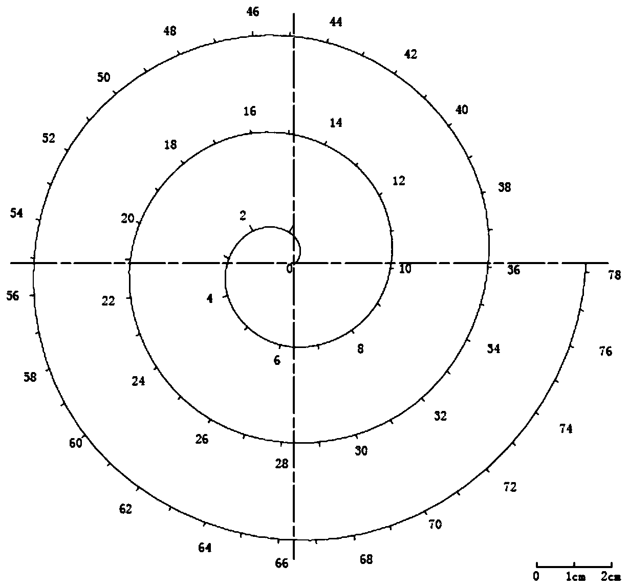
[0051] The Φ813×8.8mm X70 spiral seam submerged arc welded pipe body is prefabricated, and the real-time strain field around the depression is measured. The diameter of the prefabricated indenter is 300mm, and the depth of the prefabricated depression is 40mm. The maximum outer diameter of the depression can be calculated as 204mm.

[0052] Step 1: Determine the position of the depression to be prefabricated in the pipeline, and mark the center position of the depression on the outer wall of the pipeline. Attach the magnetic sheet of the locator to any position on the outer wall of the pipe end, and attach the magnetically adsorbed metal disc (50mm in diameter) to the corresponding position on the inner wall of the pipe end. Moving the magnetic sheet on the outer wall of the pipe drives the metal disc on the inner wall of the pipe to move to the center of the depression marked on the outer wall of the pipe;

[0053] Step 2: According to the diameter of the sag (300mm) and the ...

Embodiment 2

[0060] The Φ219×8mm 20# seamless pipe body is prefabricated, and the real-time strain field around the depression is measured. The diameter of the prefabricated indenter is 100mm, and the depth of the prefabricated depression is 22mm. The maximum outer diameter of the depression can be calculated to be 82.8mm.

[0061] Step 1: Determine the position of the depression to be prefabricated in the pipeline, and mark the center position of the depression on the outer wall of the pipeline. Attach the magnetic sheet of the locator to any position on the outer wall of the pipe end, and attach the magnetically adsorbed metal disc (20mm in diameter) to the corresponding position on the inner wall of the pipe end. Moving the magnetic sheet on the outer wall of the pipe drives the metal disc on the inner wall of the pipe to move to the center of the depression marked on the outer wall of the pipe;

[0062] Step 2: According to the diameter of the sag (100mm) and the area required to measu...


PUM

PropertyMeasurementUnit
Diameteraaaaaaaaaa
Diameteraaaaaaaaaa

Abstract

The invention discloses a strain gauge pasting and positioning method in oil and gas pipeline sunken deformation strain field measurement, which comprises the following steps: positioning the sunken center of the inner wall of a pipeline, drawing a spiral scale, and manufacturing a spiral strain gauge positioning mold according to the spiral scale; fixing a strain gauge and coating an adhesive; and pasting the strain gauge, and finally taking out the spiral strain gauge positioning mold to complete strain gauge pasting and positioning. According to the invention, a plurality of strain gauges can be simultaneously adhered to specified positions of the inner walls of pipelines with various inner diameters, and meanwhile, pasting devices for the strain gauges can be adjusted according to testrequirements, so that real-time measurement of pipeline inner wall concave strain field response is realized while an oil and gas pipeline concave defect prefabrication test is realized.

Description

technical field [0001] The invention belongs to the technical field of pipeline detection and testing, and in particular relates to a method for sticking and positioning strain gauges in the measurement of the deformation and strain field of oil and gas pipeline depressions. Background technique [0002] Oil and gas pipeline sag refers to the total deformation of the pipeline cross-section due to the permanent plastic deformation of the pipeline wall, and is one of the common forms of pipeline geometric defects. The influence of sag on the safe operation of the pipeline mainly includes four aspects: sag leads to deformation of the pipe wall, stress concentration and reduces the pressure bearing capacity or directly leads to its rupture and leakage; periodic internal pressure fluctuations may also cause fatigue damage or even fracture in the sag area; For some old pipelines with poor ductility, even if the stress concentration caused by the sag is not large, it may cause crac...

Claims


Application Information

Patent Timeline
IPC IPC(8): G01B7/16
Inventor 朱丽霞罗金恒武刚田野韩军宋成立李丽锋金剑高涛李东风
Owner BC P INC CHINA NAT PETROLEUM CORP
Learn More