Load terminal of high-voltage direct current (DC) relay

A load terminal, high-voltage direct current technology, applied in the direction of relays, electromagnetic relays, detailed information of electromagnetic relays, etc., can solve problems such as brazing failure, load terminal slippage, and connection end drop-off, so as to reduce serious heat generation and improve use reliability , to ensure the effect of verticality

Pending Publication Date: 2019-05-21
XIAMEN HONGFA ELECTRIC POWER CONTROLS
View PDF0 Cites 0 Cited by
  • Summary
  • Abstract
  • Description
  • Claims
  • Application Information

AI Technical Summary

Problems solved by technology

[0002] At present, the load terminals of high-voltage DC relays on the market mainly have the following structures: 1. The lead-out end made of oxygen-free copper is directly turned into an external thread form to form an external thread connection end, and the lead-out end needs to be brazed to the ceramic cover of the relay during production. In fact, when the oxygen-free copper hardness is reduced after high-temperature brazing, the maximum torque that the external thread connection end can bear decreases, and the torque requirement cannot be met in practical applications, resulting in the load terminal slipping or breaking, and shortening the relay. service life
2. The lead-out end and the screw made of oxygen-free copper are fixed with thread glue. Because the temperature of the lead-out end is too high during work, the glue is easy to age and cause failure
At the same time, the connection between the load terminal connection end and the lead-out end in structure 2 is to open a receiving hole on the lead-out end, insert the lower end of the connecting end into the receiving hole and then weld and fix it. Due to the limitation of the overall height, the length of the lead-out end is often shorter , the depth of the accommodation hole cannot be made very deep, so that the perpendicularity between the connection end and the end surface of the lead-out end cannot be guaranteed, and the connection end is prone to inclination during use. If the depth of the accommodation hole is deepened, the verticality between the connection end and the end surface of the lead-out end can be improved. However, due to the deepening of the accommodating hole, the thinning part of the wall thickness of the lead-out head will increase, and the conductive cross-sectional area of ​​the lead-out will become smaller, which will lead to serious heating
And in use, when the torque on the lead-out end of the external thread exceeds the maximum torque it can withstand, it will cause brazing failure and the risk of the connection end falling off

Method used


Image

  • Load terminal of high-voltage direct current (DC) relay
  • Load terminal of high-voltage direct current (DC) relay
  • Load terminal of high-voltage direct current (DC) relay

Examples


Embodiment Construction

[0025] The present invention will be further described below in conjunction with the accompanying drawings and embodiments.

[0026] In describing the present invention, it should be understood that the terms "upper", "lower", "front", "rear", "left", "right", "top", "bottom", "inner", " The orientation or positional relationship indicated by "outside", etc. is based on the orientation or positional relationship shown in the drawings, and is only for the convenience of describing the present invention and simplifying the description, rather than indicating or implying that the referred device or element must have a specific orientation, so as to Specific orientation configurations and operations, therefore, are not to be construed as limitations on the invention.

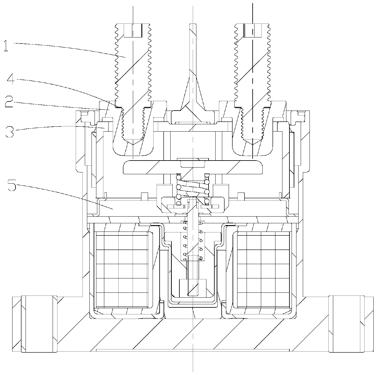
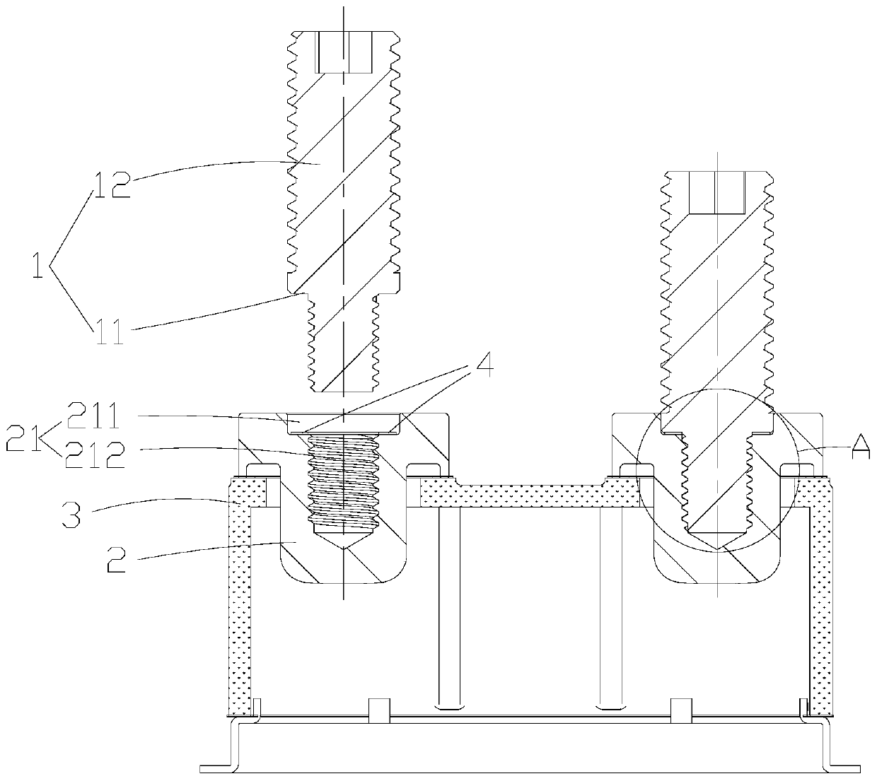
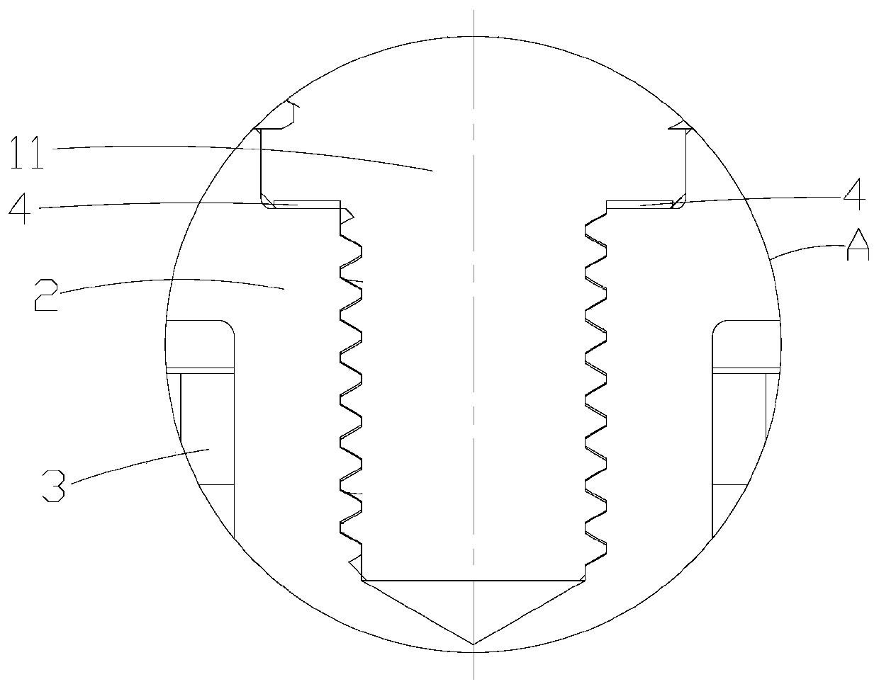
[0027] Please refer to attached figure 1 , attached figure 2 , attached image 3 , in this embodiment, a load terminal of a high-voltage direct current relay, including a connection end 1 and a lead-out end 2 ar...


PUM


Abstract

The invention discloses a load terminal of a high-voltage direct current (DC) relay. The relay comprises connecting ends, and leading-out ends arranged on a ceramic relay cover, wherein a step hole isformed in the head of each leading-out end; a step part is formed at the lower part of each connecting end, and can be adaptively inserted into the corresponding step hole; the step holes are connected with the corresponding step parts through thread fit; a brazing layer, through which each leading-out end can be connected with the corresponding connecting end, is arranged between matched step surfaces of the corresponding step hole and the corresponding step part; and double-connection structures for preventing the connecting ends from loosening and dropping are formed through the thread fitconnection between the step holes and the step parts and the brazed connection between the matched step surfaces of the step holes and the step parts. The load terminal disclosed by the invention hasthe advantages that the maximum torque bearable by the connecting ends is larger; and the double-connection structures for preventing the connecting ends from loosening and dropping are formed through the thread fit connection between the step holes and the step parts and the brazed connection between the matched step surfaces of the step holes and the step parts, so that the connecting ends canbe prevented from dropping when the brazing layers fail, and high use reliability can be further achieved.

Description

technical field [0001] The invention relates to the technical field of high voltage direct current relays, in particular to a load terminal of a high voltage direct current relay. Background technique [0002] At present, the load terminals of high-voltage DC relays on the market mainly have the following structures: 1. The lead-out end made of oxygen-free copper is directly turned into an external thread form to form an external thread connection end, and the lead-out end needs to be brazed to the ceramic cover of the relay during production. In fact, when the oxygen-free copper hardness is reduced after high-temperature brazing, the maximum torque that the external thread connection end can bear decreases, and the torque requirement cannot be met in practical applications, resulting in the load terminal slipping or breaking, and shortening the relay. service life. 2. The lead-out end and the screw made of oxygen-free copper are fixed with thread glue. Because the temperat...

Claims


Application Information

Patent Timeline
IPC IPC(8): H01H50/14
Inventor 钟叔明钟浩李敏智吴祝熊
Owner XIAMEN HONGFA ELECTRIC POWER CONTROLS
Why Eureka
Try Eureka