Low-section vertical polarization unmanned aerial vehicle antenna
A vertical polarization and UAV technology, which is applied in the direction of antenna, antenna grounding device, antenna grounding switch structure connection, etc., can solve the problems of large volume and high profile of UAV antenna, and achieve radiation performance and vertical polarization radiation performance, gain-enhancing effect
- Summary
- Abstract
- Description
- Claims
- Application Information
AI Technical Summary
Problems solved by technology
Method used
Image
Examples
Embodiment 1
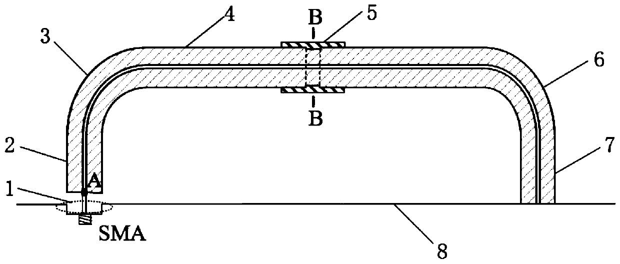
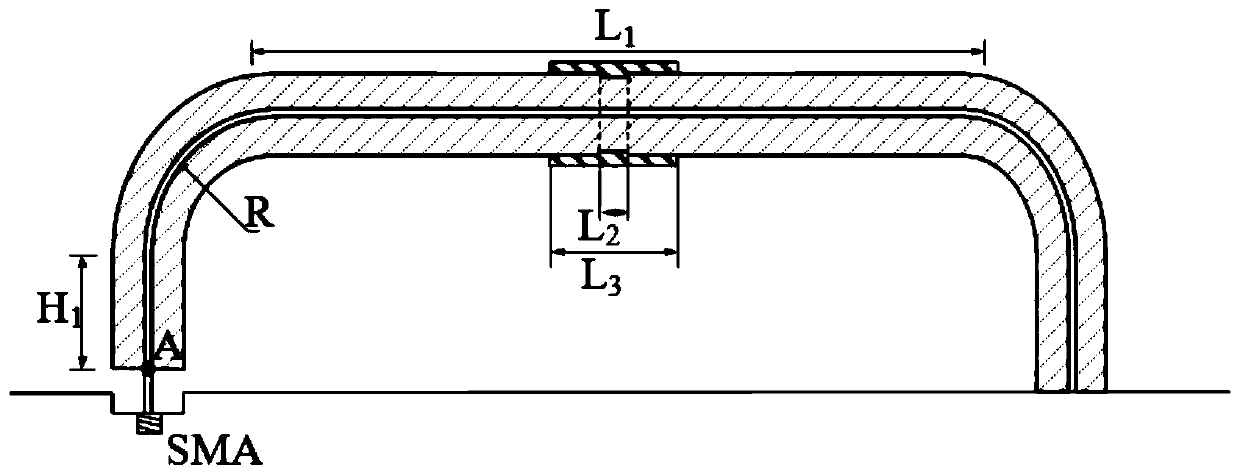
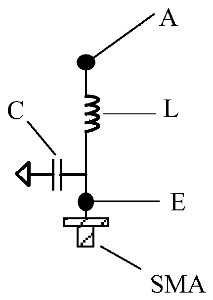
[0024] refer to figure 1 , figure 2 , image 3 and Figure 4
[0025] A low-profile vertically polarized unmanned aerial vehicle antenna, including a matching circuit 1, a feeding radiation coaxial line 2, a first bent coaxial line 3, an inductive loading line 4, a capacitive loading line 5, a second bent coaxial line axis 6, ground radiation coaxial line 7 and metal floor 8; the input end E of the matching circuit 1 is connected to an SMA connector, and the other end is connected to the feed end of the feed radiation coaxial line 2; the feed radiation The inner conductor of the feeding end of the coaxial line 2 is connected to the outer conductor, the other end is connected to one end of the first bent coaxial line 3, and the two ends of the inductive loading line 4 are respectively connected to the first bent coaxial line 3 is connected to one end of the second bent coaxial line 6, the other end of the second bent coaxial line 6 is connected to one end of the grounded r...
Embodiment 2
[0032] The inner conductor and the outer conductor of the feeding end of the feeding radiating coaxial line are connected by welding, and the lengths of the feeding radiating coaxial line 2 and the grounding radiating coaxial line 7 are both H 1 , where H 1 11.0mm to 13.0mm. h 1 is 11.0mm.
[0033]The bending radii of the conductors in the first bent coaxial line 3 and the second bent coaxial line 6 are both R, wherein R is 9.0mm˜11.0mm. R is 9.0mm.
[0034] The length of the inductive loading line 4 is L 1 , where L 1 is 78.0mm to 82.0mm, and the length of the disconnection of the outer conductor at the center position of the inductive loading line 4 is L 2 , where L 2 2.0mm to 4.0mm. L 1 78.0mm, L 2 2.0mm.
[0035] The length of the capacitive loading line 5 is L 3 , where L 3 The distance between the capacitive loading line 5 and the inductive loading line 4 is D, wherein D is 0.1mm-0.3mm. L 3 is 8.0mm and D is 0.1mm.
Embodiment 3
[0037] The inner conductor and the outer conductor of the feeding end of the feeding radiating coaxial line are connected by welding, and the lengths of the feeding radiating coaxial line 2 and the grounding radiating coaxial line 7 are both H 1 , where H 1 11.0mm to 13.0mm. h 1 is 13.0mm.
[0038] The bending radii of the conductors in the first bent coaxial line 3 and the second bent coaxial line 6 are both R, wherein R is 9.0mm˜11.0mm. R is 11.0mm.
[0039] The length of the inductive loading line 4 is L 1 , where L 1 is 78.0mm to 82.0mm, and the length of the disconnection of the outer conductor at the center position of the inductive loading line 4 is L 2 , where L 2 2.0mm to 4.0mm. L 1 82.0mm, L 2 is 4.0mm.
[0040] The length of the capacitive loading line 5 is L 3 , where L 3 The distance between the capacitive loading line 5 and the inductive loading line 4 is D, wherein D is 0.1mm-0.3mm. L 3 is 12.0mm and D is 0.3mm.
PUM
 Abstract
Description
Claims
Application Information
 - R&D
- Intellectual Property
- Life Sciences
- Materials
- Tech Scout
- Unparalleled Data Quality
- Higher Quality Content
- 60% Fewer Hallucinations
Browse by: Latest US Patents, China's latest patents, Technical Efficacy Thesaurus, Application Domain, Technology Topic, Popular Technical Reports.
© 2025 PatSnap. All rights reserved.Legal|Privacy policy|Modern Slavery Act Transparency Statement|Sitemap|About US| Contact US: help@patsnap.com


