Cable joint connection structure and connection method

A connection structure and cable joint technology, applied in welding/welding connection, connection, clamping/spring connection, etc., can solve the problems of inconvenient operation, looseness and poor connection reliability of the connection between the cable joint and the cable wire, and achieve the connection reliability. Good, easy to connect and operate, to avoid the effect of loosening

Active Publication Date: 2020-06-05
HANGZHOU SHIBANG ELECTRIC TECH CO LTD
View PDF5 Cites 0 Cited by
  • Summary
  • Abstract
  • Description
  • Claims
  • Application Information

AI Technical Summary

Problems solved by technology

[0003] The invention overcomes the disadvantages of inconvenient operation, poor connection reliability, and risk of looseness in the connection between the cable joint and the cable wire, and provides a cable joint connection structure and connection method. The connection operation between the cable joint and the cable wire is convenient, and the connection reliability is good. avoids the risk of loosening

Method used


Image

  • Cable joint connection structure and connection method
  • Cable joint connection structure and connection method
  • Cable joint connection structure and connection method

Examples


Embodiment

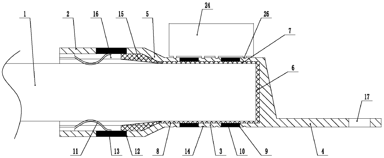
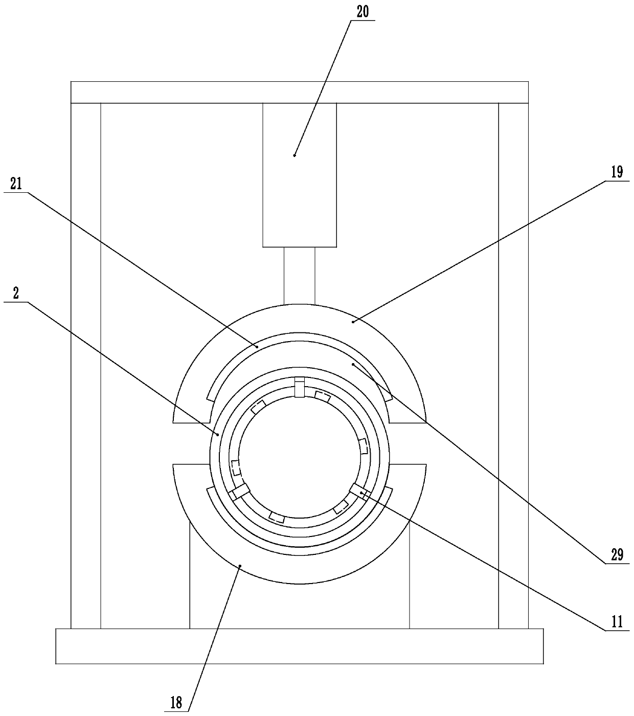
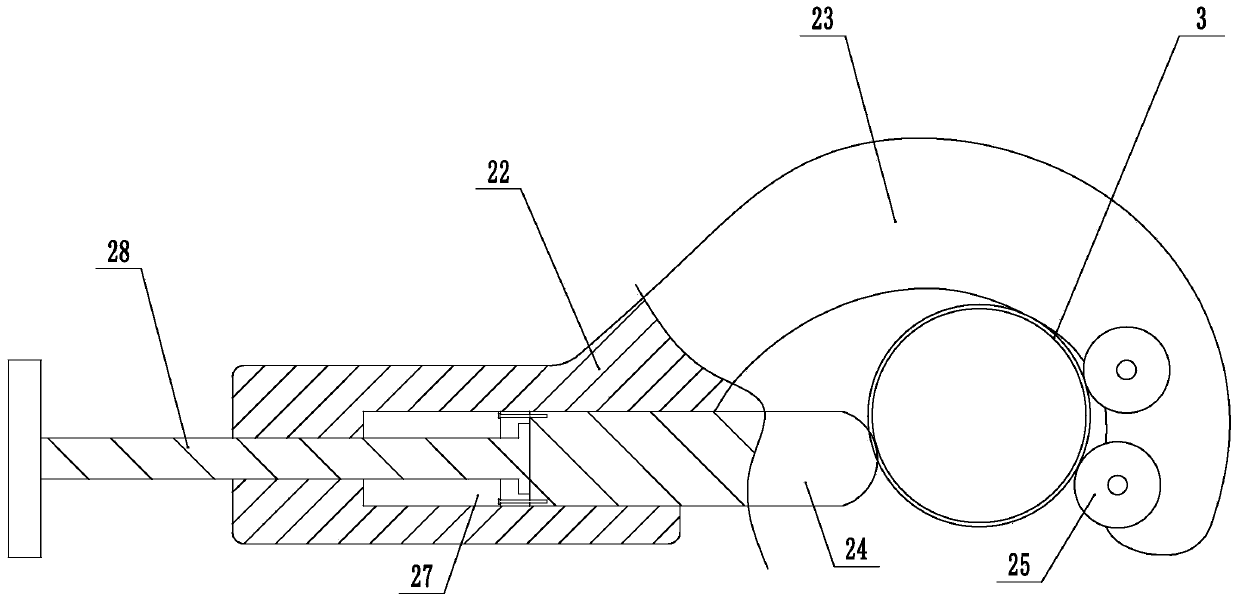
[0020] Embodiment: a kind of cable joint connection structure (see attached figure 1 ), including the connector body, the cable 1, the connector body is provided with a large-diameter tube 2, a small-diameter tube 3, and a lug 4. A transition ring 5, a solder frame is installed in the small-diameter tube, the solder frame includes a base 6, a number of support bars 7 connected to the base, and a number of axially arranged slots 8 are arranged on the inner wall of the small-diameter tube corresponding to the support bars. Adapted and inserted in the slot, the base is placed at the bottom of the small-diameter cylinder, a number of small-diameter solder baths 9 connected to the slot are provided on the outer wall of the small-diameter cylinder, and small-diameter solder blocks 10 are installed in the small-diameter solder bath; uniformly distributed on the inner wall of the large-diameter cylinder Several clamping shrapnels 11 arched inward are installed. One end of the clamping...


PUM


Abstract

The invention discloses a cable joint connecting structure and a connecting method. The disadvantages that a cable joint and a cable conductor are inconvenient for connecting operation, the connectionreliability is bad, and the loose risk is existent are solved. The connecting structure comprises the joint body and the cable conductor; a large-diameter cylinder, a small-diameter cylinder and lugplates are arranged on the joint body; a soldering frame is arranged in the small-diameter cylinder, the soldering frame comprises a base, a plurality of support strips connected to the base; a plurality of axially arranged slots are correspondingly arranged on the inner wall of the small-diameter cylinder and the support strips one by one; the support strips are inserted into the slots in an adapting manner; a plurality of small-diameter soldering slots communicating with the slots are arranged on the outer wall of the small-diameter cylinder, and small-diameter soldering blocks are arrangedin the small-diameter soldering slots; a plurality of inward arched clamping shrapnel is uniformly arranged on the inner wall of the large-diameter cylinder, one end of each inward arched clamping shrapnel is tightly connected with the inner wall of the large-diameter cylinder, the other end movably fits with the inner wall of the large-diameter cylinder; the plurality of large-diameter solderingslots are arranged on an outer wall of the large-diameter cylinder, the large-diameter soldering blocks are arranged in the large-diameter soldering slots, and the cable conductors are inserted into the large-diameter cylinder and the small-diameter cylinder.

Description

technical field [0001] The invention relates to power cable connection technology, more specifically, it relates to a cable joint connection structure and connection method. Background technique [0002] Cable connector, commonly known as copper nose, is connected to the end of the cable, and the cable connector is provided with an insertion hole. When the cable connector is connected to the cable, the end of the cable needs to be inserted into the insertion hole of the cable connector, and then pressed tightly. The cable joint makes the cable wire and the cable joint tightly connected together. Because the insertion hole on the cable connector is circular, and many cables are not circular, the outer diameter of the cable is slightly larger than the diameter of the insertion hole, which brings great difficulties to assembly. Moreover, the cable and the cable connector are tightly connected by extrusion, the connection reliability is poor, and there is a risk of loosening. ...

Claims


Application Information

Patent Timeline
Patent Type & Authority Patents(China)
IPC IPC(8): H01R4/18H01R4/20H01R4/48H01R4/02H01R11/11H01R43/048H01R43/02H01R43/00
Inventor 梁相军
Owner HANGZHOU SHIBANG ELECTRIC TECH CO LTD
Why Eureka
Try Eureka