Electrically automated anti-explosion power cabinet
A technology for electrical automation and power cabinets, which is applied in the substation/distribution device casing, and the cooling/ventilation of substations/switchgear, etc. It can solve the problems of the lack of conventional components for explosion-proof power cabinets, the generation of a large amount of smoke in the circuit, and the limited explosion-proof effect. To achieve the effect of easy fixation of the rotation angle, stable opening method, and favorable airflow discharge
- Summary
- Abstract
- Description
- Claims
- Application Information
AI Technical Summary
Problems solved by technology
Method used
Image
Examples
Embodiment 1
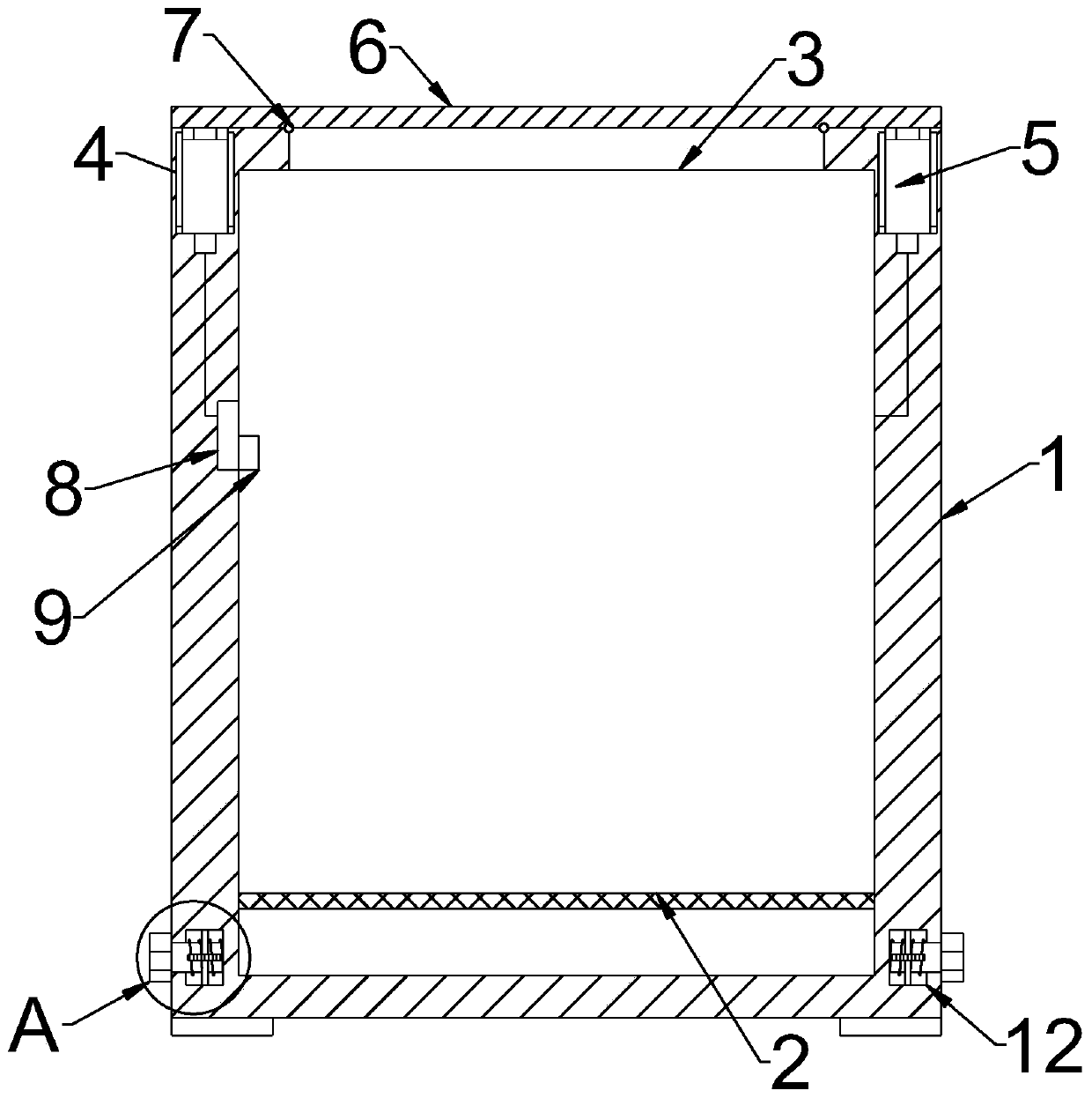
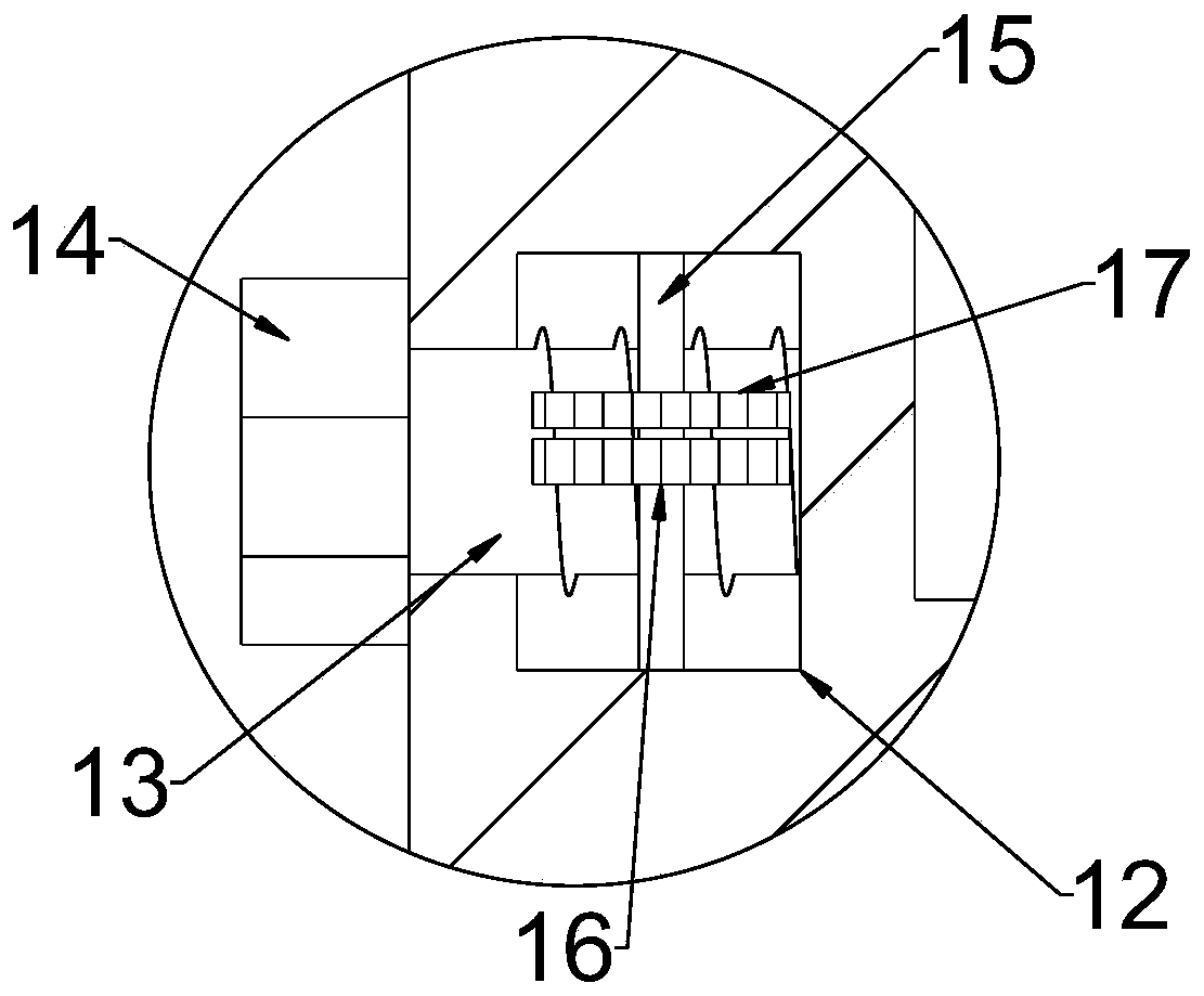
[0032] see Figure 1~3 , in an embodiment of the present invention, an electric automation explosion-proof power cabinet includes a housing 1, a gas leaking mechanism and a detection mechanism, the gas leaking mechanism includes a vent 3 provided through the upper end of the housing 1 and connected by a fuse connection assembly 5 On the explosion-proof upper cover 6 at the upper end of the housing 1 , the detection mechanism is electrically connected with the fuse connection assembly 5 .
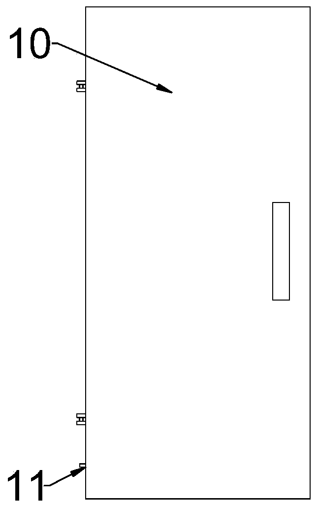
[0033] The lower part of the housing 1 is horizontally connected with a mounting plate 2, and the mounting plate 2 is fixed on the inner wall of the housing 1 by riveting or welding, and the surface of the mounting plate 2 is evenly distributed with air holes; the housing The two sides of the lower end of 1 are symmetrically provided with anti-skid support pads; the front of the housing 1 is hingedly connected to be provided with a cover door 10 that is split apart, and the lower part of the...
Embodiment 2
[0039] see Figure 4~5, in an embodiment of the present invention, an explosion-proof power cabinet for electrical automation, on the basis of Embodiment 1, the fuse connection assembly 5 is a cavity structure, and a sliding rod 51 is slidably arranged in the fuse connection assembly 5, so The bottom of the sliding rod 51 is a disc-shaped protrusion that is slidably fitted in the fuse connection assembly 5, the upper end of the slide rod 51 slides through the fuse connection assembly 5 and the end is fixedly connected with the sealing ring 7; The lower end of the sliding rod 51 and the inner bottom of the fuse connection assembly 5 are elastically connected by a compression spring 52, the compression spring 52 is in a compressed state, and the middle part of the lower end of the fuse connection assembly 5 is also assembled and connected with a fuse bolt 53. The lower end of the fuse bolt 53 slides through the lower end of the fuse connection assembly 5 and is embedded and fixe...
PUM
 Abstract
Description
Claims
Application Information
 - R&D
- Intellectual Property
- Life Sciences
- Materials
- Tech Scout
- Unparalleled Data Quality
- Higher Quality Content
- 60% Fewer Hallucinations
Browse by: Latest US Patents, China's latest patents, Technical Efficacy Thesaurus, Application Domain, Technology Topic, Popular Technical Reports.
© 2025 PatSnap. All rights reserved.Legal|Privacy policy|Modern Slavery Act Transparency Statement|Sitemap|About US| Contact US: help@patsnap.com


