Brake Control

A technology of control devices and brakes, which is applied in the direction of braking transmission devices, brakes, automatic starting devices, etc., and can solve problems such as the reduction of hydraulic braking force and the inability to maintain the braking force in the parking state

Active Publication Date: 2021-05-25
ADVICS CO LTD
View PDF8 Cites 0 Cited by
  • Summary
  • Abstract
  • Description
  • Claims
  • Application Information

AI Technical Summary

Problems solved by technology

[0006] However, in the conventional technology as described above, if the timing of reducing the hydraulic braking force and the timing of generating the parking braking force are not properly set, there is a possibility that the hydraulic pressure cannot be distributed optimally to the predetermined wheels. Power and parking braking force, but the vehicle cannot maintain the parking state due to insufficient braking force or the excess hardware load remains due to excessive braking force

Method used


Image

  • Brake Control
  • Brake Control
  • Brake Control

Examples


Embodiment Construction

[0016] Hereinafter, embodiments of the present invention will be described based on the drawings. The configuration of the embodiment described below, and the operations and results (effects) obtained by the configuration are just examples, and are not limited to the content described below.

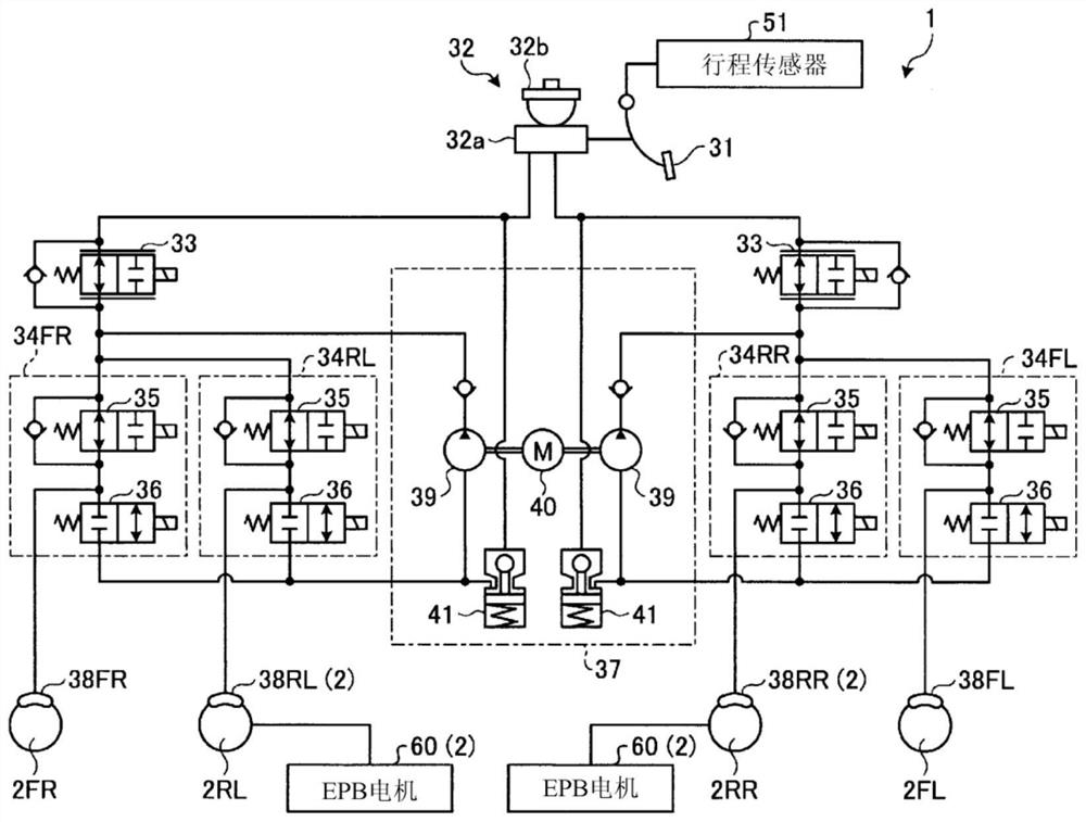
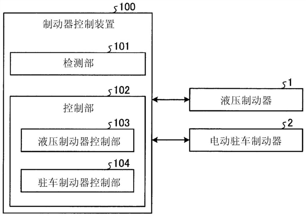
[0017] figure 1 represents the brake control device 100 as an embodiment (in figure 1 not shown, refer to the figure 2 ) is a configuration diagram illustrating an example of a schematic configuration of a brake device that is a control object. This brake device is provided, for example, in a general vehicle with four wheels.

[0018] Such as figure 1 As illustrated, the brake device according to the embodiment includes a hydraulic brake 1 and an electric parking brake 2. The hydraulic brake 1 is configured to apply braking force (friction force) to both front wheels 2FL and 2FR and rear wheels 2RL and 2RR. braking torque), the electric parking brake 2 is configured to be able to a...


PUM


Abstract

The brake control device of the embodiment is, for example, a brake control device that controls a hydraulic brake and an electric parking brake, the hydraulic brake can generate hydraulic braking force on both the front wheels and the rear wheels of a four-wheeled vehicle, and the electric parking brake can be applied to the front wheels. and one of the rear wheels generates a parking brake force different from the hydraulic brake force, and the brake control device includes: a detection unit that detects a parking brake operation for causing the electric parking brake to generate the parking brake force; and The control unit causes the electric parking brake to generate the parking brake force before generating the parking brake force when the control unit detects the operation of the parking brake in a state in which the vehicle is maintained in a stopped state only by the hydraulic braking force generated by both the front and rear wheels. The hydraulic braking force generated at the one wheel is reduced, and the hydraulic braking force generated at the other wheel other than the one wheel is adjusted to a magnitude sufficient to maintain the stopped state.

Description

technical field [0001] The invention relates to a brake control device. Background technique [0002] Conventionally, in order to reduce the load caused by repeatedly generating the hydraulic braking force by the hydraulic brake and the parking braking force by the electric parking brake on predetermined wheels, it has been proposed to reduce the hydraulic braking force when the electric parking brake is operating. technology. [0003] prior art literature [0004] patent documents [0005] Patent Document 1: US Registered Patent No. 8494745 [0006] However, in the conventional technology as described above, if the timing of reducing the hydraulic braking force and the timing of generating the parking braking force are not properly set, there is a possibility that the hydraulic pressure cannot be distributed optimally to the predetermined wheels. Power and parking braking force, and the vehicle cannot maintain the parking state due to insufficient braking force, or exce...

Claims


Application Information

Patent Timeline
Patent Type & Authority Patents(China)
IPC IPC(8): B60T7/12B60T13/74
CPCB60T7/12B60T13/74B60T13/662B60T2270/402B60T8/32B60T8/17B60T13/588B60T13/741
Inventor 浦冈照薫中野启太浦野达也
Owner ADVICS CO LTD
Why Eureka
Try Eureka