Nuclear reactor detector assembly dismounting system, control system and control method

A detector assembly, a technology for nuclear reactors, applied in the directions of reactor fuel elements, reactors, nuclear engineering, etc., can solve problems such as no control system involved, different shearing and winding working methods, etc.

Active Publication Date: 2021-01-22
NUCLEAR POWER INSTITUTE OF CHINA
View PDF13 Cites 0 Cited by
  • Summary
  • Abstract
  • Description
  • Claims
  • Application Information

AI Technical Summary

Problems solved by technology

In the Hualong No. 1 reactor, the equipment described in the patent "a detector assembly removal process and its special removal equipment" (Sichuan, CN107767976A[P].2018-03-06) is used for the removal of detector assemblies. However, it is different from the equipment composition, shearing and winding structure and shearing and winding working method involved in the present invention, and does not involve the description of the control system

Method used


Image

  • Nuclear reactor detector assembly dismounting system, control system and control method
  • Nuclear reactor detector assembly dismounting system, control system and control method
  • Nuclear reactor detector assembly dismounting system, control system and control method

Examples


Embodiment 1

[0209] see Figure 14-Figure 17 As shown, the dismantling device for the nuclear reactor detector assembly is composed of the following components in combination and modularization,

[0210] Detector component gripper 1, large and small car components 2, shearing and winding device 3, vision centering device 4, monitoring device 5, high storage container and storage rack 6; among them,

[0211] The large and small cart assembly 2 is arranged in the nuclear reactor and is located directly above the detector assembly; the large and small cart assembly 2 includes a cart 202 moving in the Y direction and a trolley 204 moving in the X direction, and the cart 204 is assembled on the cart 202;

[0212] The detector assembly gripper 1 is configured on the upper top surface of the trolley 204. The detector assembly gripper 1 includes an outer cylinder assembly 105 whose longitudinal axis is arranged along the Z direction, and a gripper assembly 104 that moves up and down along the oute...

Embodiment 2

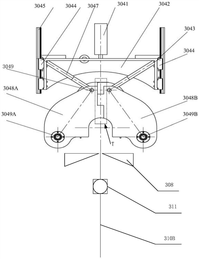
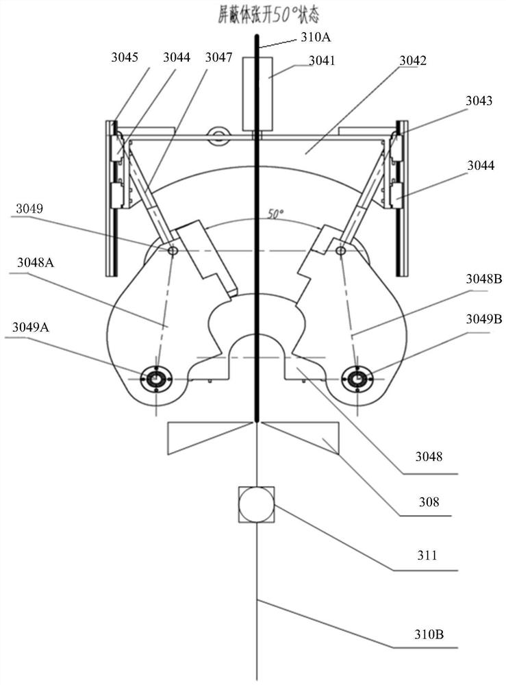
[0247] On the basis of the above examples, if figure 1 , figure 2 as shown,

[0248] Such as figure 1 , figure 2 Schematic side view of the shielding structure for removal of the nuclear reactor detector assembly.

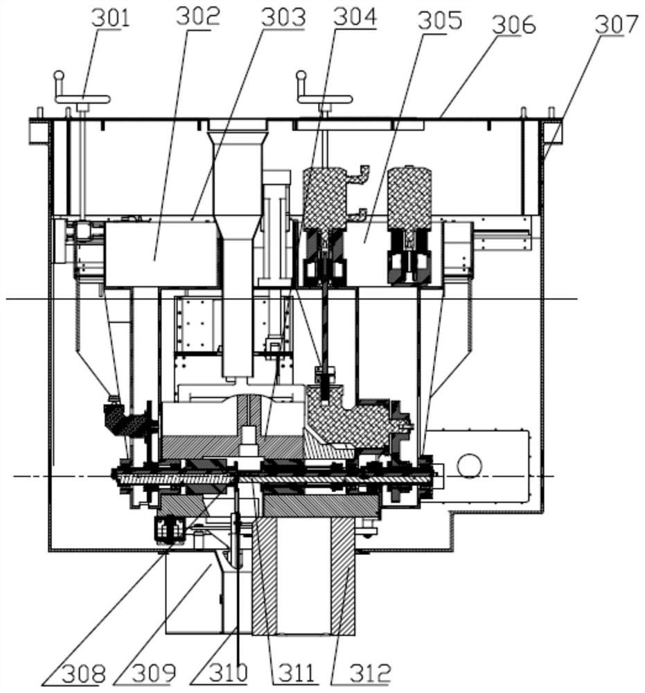
[0249] figure 1 and figure 2 The shield structure shown is image 3 The shielding structure 304 in.

[0250] The subsequent front and back refer to the direction facing the legend paper and the direction facing away from the paper as shown in the figure.

[0251] Shield structures, including:

[0252] The left shield body 3048A, the right shield body 3048B, the left shield shaft 3049A, and the right shield shaft 3049B; the left shield body 3048A is rotatably connected around the left shield shaft 3049A, and the right shield body 3048B is rotatably connected around the right shield shaft 3049B; the left shield body Shaft 3049A and right shielding shaft 3049B are at the same level. The distance between left shielding shaft 3049A and right shielding shaft ...

Embodiment 3

[0336] Such as Figure 18 , Figure 19 , Figure 20 shown;

[0337] Nuclear reactor detector component removal control system, including process operation control device, detector component gripper control device, large and small car body control device, cutting and winding device control device, and data transmission unit;

[0338] The process operation control device is used to generate rough positioning data and coarse positioning commands, fine positioning data and fine positioning commands under the trigger positioning command and send them to the control device of the large and small vehicle body, and the control device of the large and small vehicle body is used to Drive the large and small car components for coarse positioning with the coarse positioning command, and drive the large and small car components for fine positioning according to the fine positioning data and fine positioning commands;

[0339] The process operation control device is used to send the grab...


PUM


Abstract

The invention discloses a detector assembly dismounting control system and a corresponding control method, and further provides a nuclear reactor detector assembly dismounting system composed of a nuclear reactor detector assembly dismounting device and a corresponding nuclear reactor detector assembly dismounting control system. The nuclear reactor detector assembly dismounting device is used forpulling out the high-radioactivity detector assembly at the end of the service life from a channel of an upper reactor internals guide structure, placing the high-radioactivity detector assembly intoa special container after complete continuous actions such as shielding, shearing and winding, and transferring the high-radioactivity detector assembly to a specified treatment place. The purposes of continuous operation, safety and high efficiency are achieved. The corresponding detector assembly dismounting control system can achieve control operations such as positioning, grabbing, shearing (shielding), winding, transferring and the like.

Description

technical field [0001] The invention relates to the technical field of dismantling of reactor equipment, in particular to a control system and a control method for dismantling a nuclear reactor detector assembly. Background technique [0002] The instruments used in the core measurement system in the second-generation and second-generation pressurized water reactor nuclear power plants are divided into instrument thermocouples for temperature measurement and instrument neutron flux detectors for neutron flux measurement. The thermocouple is introduced from the top cover of the pressure vessel, guided by the thermocouple column assembly, and positioned at the specified measuring point position, and the lower end of the thermocouple is located at the core outlet of the upper core plate. The neutron flux detector is introduced from the bottom head of the pressure vessel, guided through the instrument casing and finger casing when necessary, and enters the guide pipe inside the ...

Claims


Application Information

Patent Timeline
Patent Type & Authority Applications(China)
IPC IPC(8): G21C19/02G21C19/105G21C19/20
CPCG21C19/02G21C19/105G21C19/207Y02E30/30
Inventor 安彦波李娜瓮松峰湛卉杨其辉余志伟罗英钟元章张翼王尚武熊思勇黄宗仁李燕任荷王炳炎
Owner NUCLEAR POWER INSTITUTE OF CHINA
Why Eureka
Try Eureka