Underwater building defect detection method based on autonomous navigation technology

A technology for autonomous navigation and defect detection, which is applied in the direction of optical testing of defects/defects, instruments, and analysis of solids using sound waves/ultrasonic waves/infrasonic waves. The effect of flexibility

Pending Publication Date: 2020-04-10
NANJING UNIV OF POSTS & TELECOMM
View PDF6 Cites 2 Cited by
  • Summary
  • Abstract
  • Description
  • Claims
  • Application Information

AI Technical Summary

Problems solved by technology

As a kind of underwater robot, ROV has the advantages of strong adaptability, long battery life, and strong load capacity, but it needs to be remotely controlled manually through cables, which increases the workload of operators.

Method used


Image

  • Underwater building defect detection method based on autonomous navigation technology

Examples


Embodiment Construction

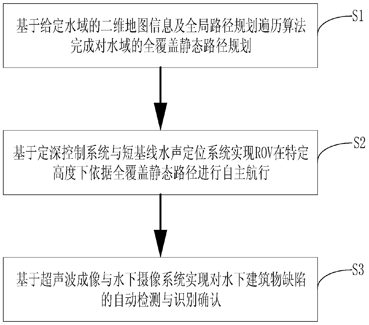
[0013] see figure 1 , the present embodiment provides a method for detecting defects of underwater structures based on autonomous navigation technology, including the following steps,

[0014] Step S1, based on the two-dimensional map information of the given water area, perform full-coverage path planning for the water area to be measured through the combing traversal algorithm;

[0015] Step S2, realizing the autonomous navigation of the ROV in the three-dimensional underwater space through the depth control system, the attitude control system, the motion control system and the short baseline underwater acoustic positioning system;

[0016] Step S3 , detecting and identifying defects of underwater structures through ultrasonic imaging and underwater camera systems.

[0017] In step S1, obtain the two-dimensional map information of the water area to be measured, set the boundary of the water area to be measured, determine the path planning traversal mode and path starting po...


PUM


Abstract

An underwater building defect detection method based on an autonomous navigation technology comprises the following steps: S1, based on two-dimensional map information of a given water area, carryingout full-coverage path planning on a to-be-detected water area through a full-coverage path planning traversal algorithm; S2, realizing autonomous navigation of the ROV in a three-dimensional underwater space through a depth setting control system, an attitude control system, a motion control system and a short baseline acoustic positioning system; and S3, performing defect detection and identification determination on the underwater building through ultrasonic imaging and an underwater camera system. According to the method, the autonomous navigation technology and the ROV are combined, and the control burden of remote manual control is reduced. Meanwhile, the definition of collected images is improved through the combination of the ultrasonic imaging technology and the underwater camerashooting technology, and the defect detection accuracy is improved.

Description

technical field [0001] The invention belongs to the technical field of underwater robots, and in particular relates to an underwater building defect detection method based on autonomous navigation technology. Background technique [0002] As one of the key technologies of autonomous navigation, path planning technology can be divided into global path planning and local dynamic path planning according to the planning stage. Global planning is carried out on the premise that the environmental information is completely known, and the optimal solution to complete the task is obtained through global planning. Local planning is based on the unknown local environment, real-time perception of the current environment through sensors, and local obstacle avoidance through local dynamic planning. The combination of global planning and local dynamic programming can be used as a solution for autonomous navigation. As a kind of underwater robot, ROV has the advantages of strong adaptabil...

Claims


Application Information

Patent Timeline
Patent Type & Authority Applications(China)
IPC IPC(8): G05D1/06G01N29/04G01N21/88
CPCG05D1/0692G01N29/04G01N21/88
Inventor 孙宁李茂如刘浏李晓飞
Owner NANJING UNIV OF POSTS & TELECOMM
Why Eureka
Try Eureka