
Liquid crystal display device

A technology of liquid crystal display device and liquid crystal layer, which is applied in the direction of instruments, polarizing elements, optics, etc., to achieve the effect of improving the viewing angle characteristics

Active Publication Date: 2020-10-02
NITTO DENKO CORP
View PDF11 Cites 0 Cited by
  • Summary
  • Abstract
  • Description
  • Claims
  • Application Information

AI Technical Summary

Problems solved by technology

However, in conventional liquid crystal display devices, control of viewing angle characteristics is substantially only performed symmetrically with respect to the front direction ((φ, θ)=(0°, 0°)).

Method used

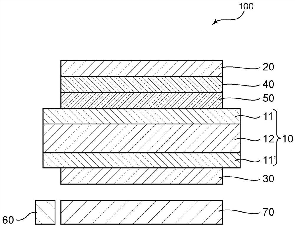

Image

  • Liquid crystal display device

Examples


Embodiment Construction

[0019] Hereinafter, embodiments of the present invention will be described with reference to the drawings, but the present invention is not limited to these embodiments.

[0020] (Definition of terms and symbols)

[0021] Definitions of terms and symbols used in this specification are as follows.

[0022] (1) Refractive index (nx, ny, nz)

[0023] "nx" is the refractive index in the direction in which the in-plane refractive index becomes the largest (that is, the slow axis direction), "ny" is the refractive index in the in-plane direction perpendicular to the slow axis (that is, the fast axis direction), and "nz" is the refractive index in the thickness direction.

[0024] (2) In-plane retardation (Re)

[0025] "Re(λ)" is an in-plane retardation measured by light having a wavelength of λnm at 23°C. When the thickness of the layer (thin film) is set to d (nm), Re(λ) is obtained by the formula Re=(nx-ny)×d. For example, "Re(550)" is an in-plane retardation measured by ligh...


PUM

PropertyMeasurementUnit
thicknessaaaaaaaaaa
thicknessaaaaaaaaaa
thicknessaaaaaaaaaa

Abstract

Provided is a liquid crystal display device having improved viewing angle characteristics in a region that is vertically asymmetric with respect to the front horizontal direction. The liquid crystal display device of the present invention includes: a liquid crystal cell having a liquid crystal layer including liquid crystal molecules aligned in a planar alignment in the absence of an electric field; and a first polarizer disposed on the liquid crystal. The visual confirmation side of the unit; the second polarizer, the second polarizer is arranged on the back side of the liquid crystal unit; the first optical compensation layer, the first optical compensation layer is arranged between the liquid crystal unit and the first polarizer and a second optical compensation layer, the second optical compensation layer is disposed between the liquid crystal unit and the first optical compensation layer. The refractive index nz in the thickness direction of the first optical compensation layer 1 is less than 1.5187, and the refractive index nz in the thickness direction of the second optical compensation layer 2 Less than 1.5340.

Description

technical field [0001] The present invention relates to a liquid crystal display device. Background technique [0002] Liquid crystal display devices are used as display units for various instruments, navigation systems, and the like that are arranged on the sub-dashboard of automobiles. Such a vehicle-mounted liquid crystal display device is mainly visually recognized by the driver, so it is displaced to the four corners of a predetermined area on the upper side compared with the front direction (for example, (angle of view φ in the vertical direction, angle of view θ in the horizontal direction) = (+20°, +50°), (+20°, -50°), (-20°, +50°) and (-20°, -50°)) display characteristics (such as contrast and color tone) change important. However, in the conventional liquid crystal display device, substantially only the control of the viewing angle characteristic is performed symmetrically with respect to the front direction ((φ, θ)=(0°, 0°)). Therefore, a liquid crystal display...

Claims


Application Information

Patent Timeline
Patent Type & Authority Patents(China)
IPC IPC(8): G02F1/13363G02B5/30
CPCG02B5/30G02F1/13363G02F1/133634G02F2413/02G02F2413/06G02F2413/12G02F1/133528G02F2413/08G02F1/133538G02F1/133562G02F1/133567
Inventor 河村亮渊田岳仁高田胜则北村吉绍
Owner NITTO DENKO CORP
Learn More