
A conveying device that uses conveying airflow to control the process of material throwing

A technology for conveying air flow and conveying device, which is applied in the field of agricultural machinery, can solve problems such as collision, and achieve the effects of reducing the collision damage rate, improving the utilization rate of air flow, and saving energy.

Active Publication Date: 2020-05-22
NANJING AGRI MECHANIZATION INST MIN OF AGRI
View PDF10 Cites 0 Cited by
  • Summary
  • Abstract
  • Description
  • Claims
  • Application Information

AI Technical Summary

Problems solved by technology

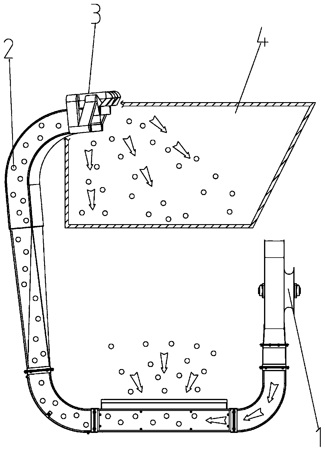
[0006] The object of the present invention is to provide a conveying device that uses conveying airflow to control the material throwing process, which can separate materials and conveying airflow during the process of conveying materials, and use conveying airflow to control the throwing direction and speed of materials, which solves the problem of material being conveyed. The problem of collision occurs, and the requirement of on-demand distribution of material stacking can be realized

Method used


Image

  • A conveying device that uses conveying airflow to control the process of material throwing
  • A conveying device that uses conveying airflow to control the process of material throwing
  • A conveying device that uses conveying airflow to control the process of material throwing

Examples


Embodiment Construction

[0038]The present invention will be further described below in conjunction with the accompanying drawings and specific embodiments.

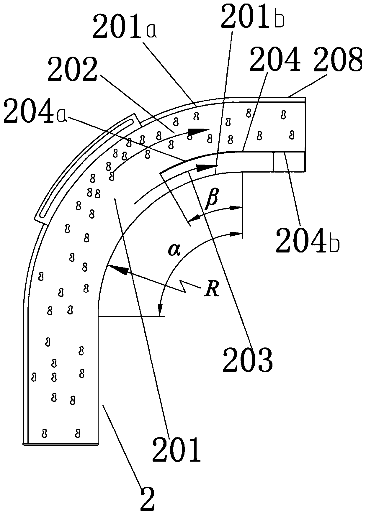
[0039] like Figure 1-10 As shown, a conveying device that utilizes conveying air flow to control the material throwing process includes a conveying pipeline 2, the feed pipe section of the conveying pipeline 2 is connected to an air source equipped with a large centrifugal fan 1, and the discharge pipe section 208 of the conveying pipeline 2 is set on the top And it is at the position of the upper feeding side of the silo 4.

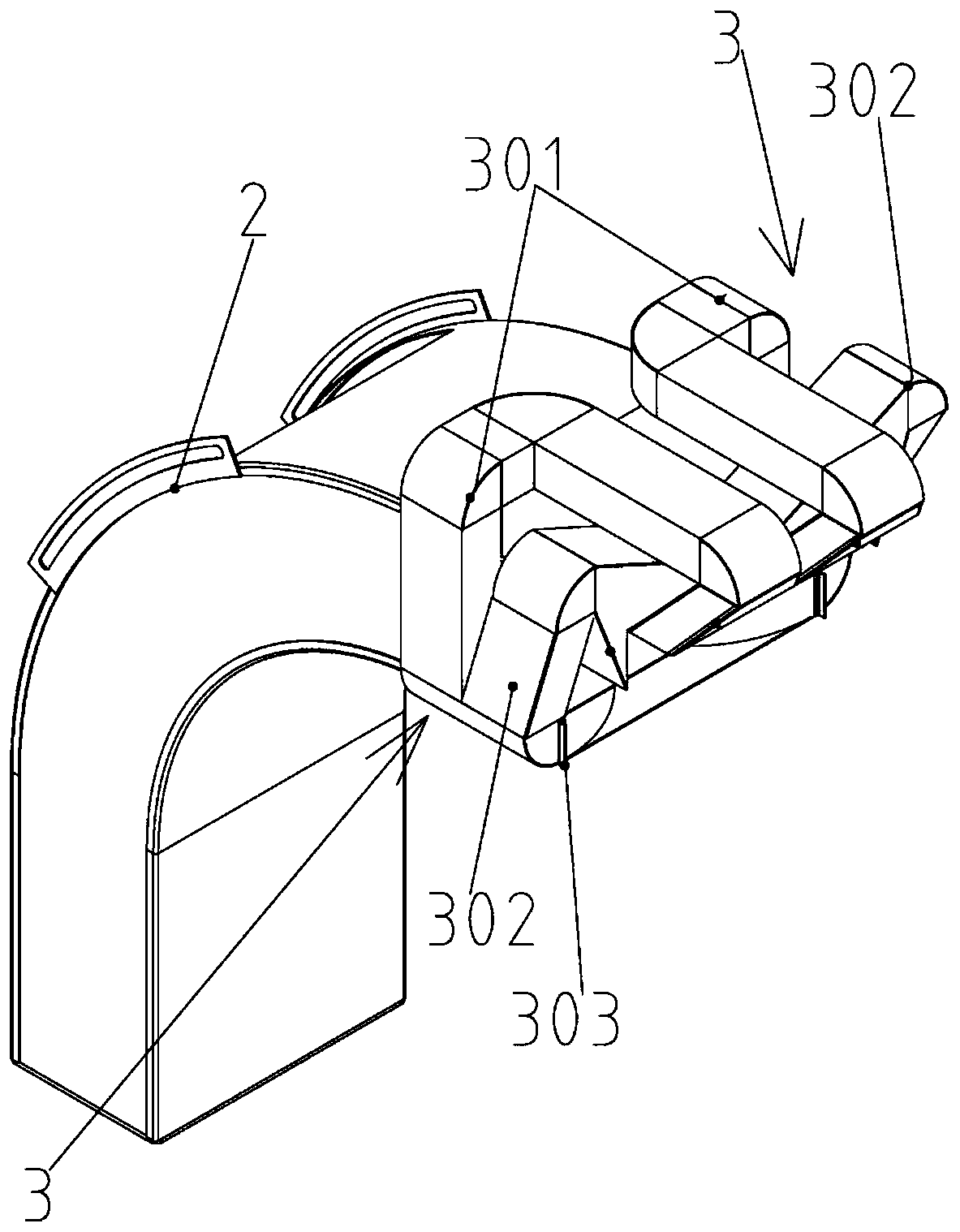
[0040] The discharge pipe section 208 of the above-mentioned conveying pipeline 2 is equipped with a pair of guide pipe groups 3 in the direction of falling material. Based on the angle of view perpendicular to the outlet end face of the discharge pipe section 208, the two guide pipe groups 3 in the direction of discharge are respectively arranged at the ends of the conveying pipe 2. On the left and right sides of the di...


PUM


Abstract

The invention relates to a conveying device using conveying airflow to control the material throwing process in the technical field of agricultural machinery. The conveying device using the conveyingairflow to control the material throwing process comprises a conveying pipeline. A discharging pipe of the conveying pipeline is distributed with a pair of blanking direction guiding pipe sets, the conveying pipeline is distributed with parts used for separating materials from conveying airflow, the parts comprises partition plates arranged in the conveying pipeline, the inner cavity of the conveying pipeline is divided into a material channel and a pure airflow channel through the partition plates; and each blanking direction guiding pipe set comprises an airflow blockage multi-way pipe usedfor decreasing the ejecting speed of the materials and a pair of guiding airflow multi-way pipes oppositely arranged, the airflow blockage multi-way pipe and the guiding airflow multi-way pipes communicate with the pure airflow channel, the two airflow guiding multi-way pipes are used for generating guiding airflow and guiding the throwing direction of the materials, thus the materials and the conveying airflow can be separated in the process of material conveying, the conveyed airflow is used for controlling the throwing direction and speed of the materials, and thus the crushing action of the materials is remarkably reduced during conveying.

Description

technical field [0001] The invention relates to the technical field of agricultural machinery, in particular to a pneumatic conveying system of peanut combined harvesting equipment. Background technique [0002] Peanut is an important oil crop and protein resource in China. Its perennial planting area and total output rank top two in the world, and it is one of China's advantageous agricultural products. With the development of large-scale production in traditional main production areas and Xinjiang, Northeast and other regions, the demand for high-efficiency peanut harvesting equipment is urgent. Introduced a series of equipment for large-scale combined peanut harvesting. [0003] The granular material conveying devices at home and abroad generally adopt three forms: pneumatic conveying, scraper lifting chain, and screw auger conveying. During joint harvesting of peanuts, the peanut pods after fruit picking and cleaning need a special conveying device to transport them to...

Claims


Application Information

Patent Timeline
Patent Type & Authority Patents(China)
IPC IPC(8): B65G53/16B65G53/58B65G53/36B65G53/34B65G53/52
Inventor 于昭洋曹明珠胡志超王申莹张鹏徐弘博吴峰顾峰玮陈有庆施印炎
Owner NANJING AGRI MECHANIZATION INST MIN OF AGRI
Learn More