
Ice cube tray auxiliary structure for assisting ice cubes in falling through ice cube tray swinging

An auxiliary structure and ice-making tray technology, applied in ice making, ice making, application, etc., can solve the problems of ice cubes sticking to the inside of the ice-making tray, unable to drop ice cubes, and unable to drop ice cubes

Active Publication Date: 2019-05-24
山东宝成制冷设备有限公司
View PDF4 Cites 0 Cited by
  • Summary
  • Abstract
  • Description
  • Claims
  • Application Information

AI Technical Summary

Problems solved by technology

[0006] In order to solve the above-mentioned technical problems, the present invention provides an auxiliary ice-making tray structure that uses the swing of the ice-making tray to assist the ice cubes to fall, so as to solve the problem that the existing ice-making trays are usually automatically forced to rotate, and the ice-making trays are rotating At this time, only one end of the ice tray is rotated, resulting in a smaller rotation arc at the end of the ice tray rotation axis, and the ice cubes are easy to stick to the inside of the ice tray due to the small rotation arc, so that the ice cubes inside the ice tray cannot fall To the inside of the ice maker, and the existing ice trays generate a certain pressure when rotating, so that the existing ice trays cannot use the ice trays to swing and rotate to assist the ice cubes to fall

Method used


Image

  • Ice cube tray auxiliary structure for assisting ice cubes in falling through ice cube tray swinging
  • Ice cube tray auxiliary structure for assisting ice cubes in falling through ice cube tray swinging
  • Ice cube tray auxiliary structure for assisting ice cubes in falling through ice cube tray swinging

Examples


Embodiment

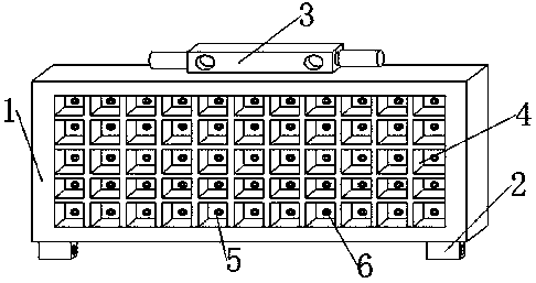
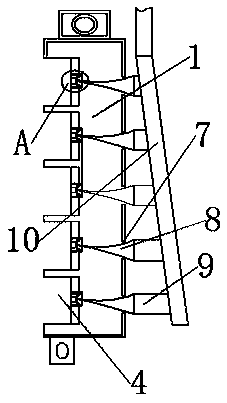
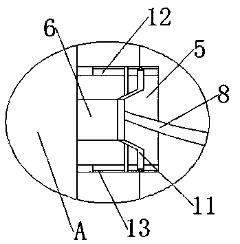
[0026] Embodiment: An auxiliary ice-making tray structure that utilizes the swing of the ice-making tray to assist ice cubes to fall, including an ice tray 1, a movable part 2 and a fixed part 3, and the movable part 2 and the fixed part 3 are respectively arranged on two sides of the ice tray 1. At the end, the ice tray 1 is embedded with an ice groove 4, and the inside of the ice groove 4 is penetrated with a fixed column 5. The inner wall of the fixed column 5 is embedded with a sliding track 12, and one side of the sliding track 12 is embedded with an inner sliding track 13, and the inner sliding The inside of the track 13 slides with an inner sliding column 15, the inside of the sliding track 12 slides with a through plate 14 and a sliding frame 11 respectively, one side of the fixed column 5 is penetrated with a through groove 7, and the inside of the fixed column 5 is provided with a sliding column 6, One side of the sliding column 6 is provided with a top column 8 , one...


PUM


Abstract

The invention provides an ice cube tray auxiliary structure for assisting ice cubes in falling through ice cube tray swinging. The ice cube tray auxiliary structure comprises an ice-tray, movable pieces and a fixed piece; the movable pieces and the fixed piece are arranged at the two ends of the ice-tray correspondingly; ice grooves are formed in the ice-tray in an embedded mode, and fixed columnsare arranged in the ice grooves in a penetrating mode; sliding rails are arranged in the inner walls of the fixed columns in an embedded mode, and inner sliding rails are arranged in one sides of thesliding rails in an embedded mode; and inner sliding columns slide in the inner sliding rails. Jacking columns are arranged, thus the inner sliding columns can be each in an equilateral triangle shape through the jacking columns, when the ice-tray rotates, the sliding columns slide into the fixed columns, the pressure on the sliding columns can be increased through the jacking columns, the sliding columns can be assisted through the pressure generated during rotation of the ice-tray inn sliding into the ice grooves, the situation that when an existing ice-tray rotates, one end of a rotary shaft of the ice-tray swings a little, and consequently the ice cubes have certain adsorption force and then adhere to the interior of the ice-tray is avoided, and thus the ice-tray can assist the ice cubes in falling through the pressure generated during swinging of the ice-tray.

Description

technical field [0001] The invention belongs to the technical field of ice making machines, and in particular relates to an ice making tray. Background technique [0002] The ice maker is a machine for making ice cubes. It usually needs to flow clean water to the inside of the ice-making tray for cooling and solidification, and force the ice-making tray to be twisted to facilitate the ice cubes inside the ice-making tray to drop into the ice machine. stored internally. [0003] Most of the ice-making trays in the prior art have the following problems in use: [0004] The existing ice-making trays are usually forced to rotate automatically, and when the ice-making trays are rotating, only one end of the ice-making trays is rotated, resulting in a smaller rotation arc at the end of the ice-making tray’s rotating shaft, and making the ice cubes easy to rotate due to The arc is small and adheres to the inside of the ice-making tray, so that the ice cubes inside the ice-making ...

Claims


Application Information

Patent Timeline
Patent Type & Authority Applications(China)
IPC IPC(8): F25C1/246
Inventor 陈成
Owner 山东宝成制冷设备有限公司
Learn More