Eureka AIR delivers breakthrough ideas for toughest innovation challenges, trusted by R&D personnel around the world.

A device and working method for measuring the height difference distribution of vehicle jumping at the bridge head

A technology for bridge head jumping and measuring parts, which is applied in the direction of measuring devices, mechanical devices, height/horizontal measurement, etc. It can solve the problems of high measurement cost, high maintenance cost, and difference in settlement, and achieve comprehensive data collection and low workload. The effect of small and few operation steps

Active Publication Date: 2020-12-22
河北锐驰交通工程咨询有限公司
View PDF7 Cites 0 Cited by
  • Summary
  • Abstract
  • Description
  • Claims
  • Application Information

AI Technical Summary

Problems solved by technology

Under the action of vehicle load, structural self-weight, and natural factors, the bridge and the road settle at the same time, but the settlement of the two is very different. The settlement of the road is much larger than the settlement of the bridge, forming a staggered platform, resulting in a bridge head when driving. jump car
[0005] Most of the traditional bridge-head vehicle jump measurement methods are based on road flatness measurement methods, such as three-meter ruler method, level measurement method, continuous flatness meter, bump accumulator, etc. These measurement methods generally have slow measurement speed and high measurement cost problems, especially equipment such as continuous levelness meter and bump accumulator are expensive and costly to maintain, and are only used in some important road measurements

Method used


Image

  • A device and working method for measuring the height difference distribution of vehicle jumping at the bridge head
  • A device and working method for measuring the height difference distribution of vehicle jumping at the bridge head
  • A device and working method for measuring the height difference distribution of vehicle jumping at the bridge head

Examples


Embodiment Construction

[0052] The present invention will be described in further detail below in conjunction with the accompanying drawings.

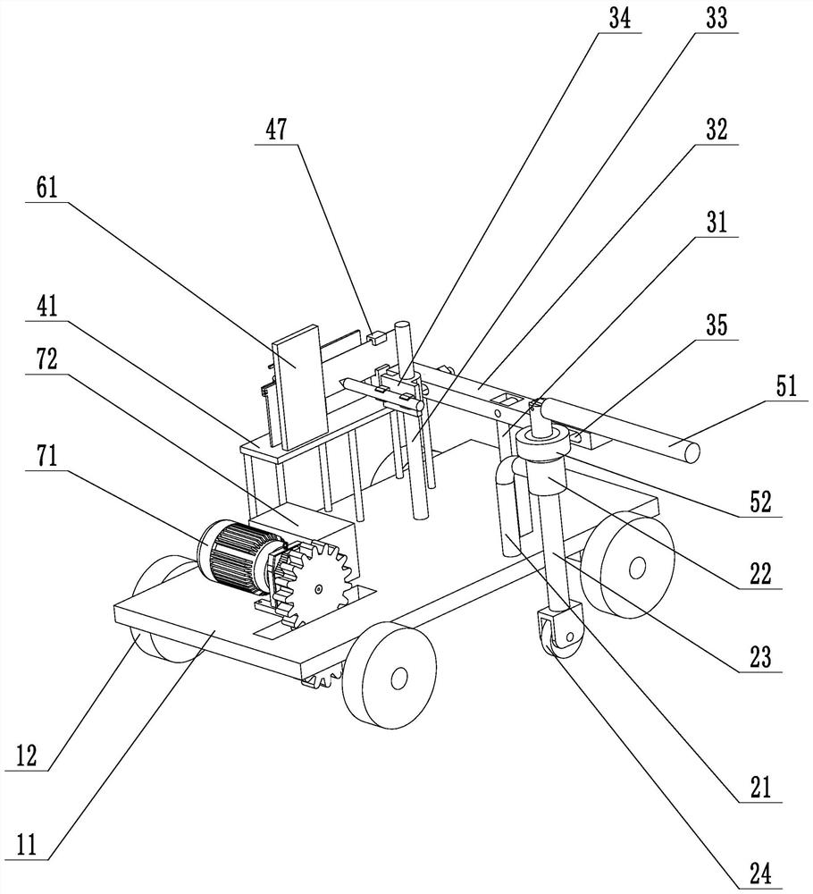
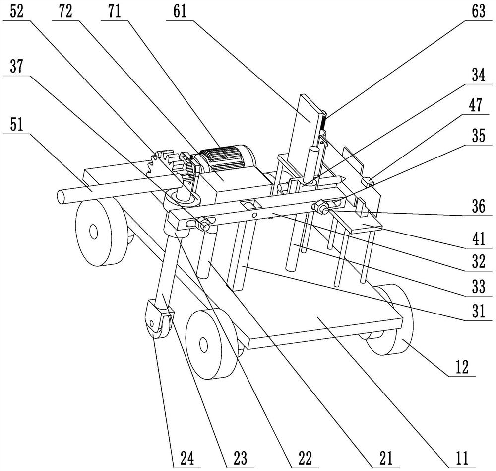
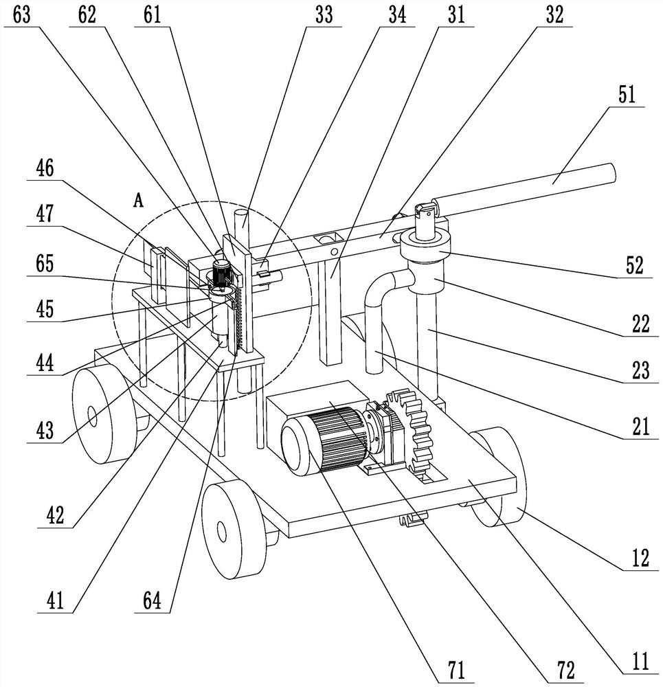
[0053] refer to figure 1 and figure 2 , is a device for measuring the height difference distribution of the bridge head jumping disclosed by the present invention, which includes a mobile base 11 and a measuring part, an amplifying part and a recording part arranged thereon.

[0054] Four directional wheels 12 are installed on the mobile base 11, and the specific connection method is: two groups of four bearing seats in total are installed on the bottom surface of the mobile base 11, and each group of bearing seats is connected with a rotating shaft, and the four directional wheels 12 They are respectively installed at the two ends of the two transmission shafts. Drive motor 71 is installed on the surface of mobile base 11, and a drive gear is installed on its output shaft, and a driven gear is installed on one of them rotating shaft, and drive gear meshes...


PUM


Abstract

The invention relates to a device for measuring bump height difference distribution at a bridge head and a working method of the device. The device comprises a movable base and directional wheels arranged on the movable base, wherein the movable base is provided with a measuring part used for feeding back the fluctuation degree of a road surface, an amplifying part used for amplifying an output signal of the measuring part and a recording part used for recording the output signal of the amplifying part. The measuring part comprises a support fixed on the movable base, a sliding sleeve vertically fixed on the support, a sliding shaft slidably connected with the sliding sleeve and a roller arranged at the lower end of the sliding shaft. The amplifying part comprises a stand column arranged on the movable base, a connecting beam hinged to the stand column, a sliding column arranged on the movable base and a clamping seat slidably connected with the sliding column. When used, the device ispushed to advance along a measuring route, the value of the height difference between the bridge head and the road surface on the modified route can be completely recorded, and the device has the characteristics of simplicity in operation, comprehensive data acquisition and high acquisition speed.

Description

technical field [0001] The invention relates to the technical field of data acquisition of vehicle jumps at the bridge head, in particular to a device for measuring the height difference distribution of vehicle jumps at the bridge head and a working method thereof. Background technique [0002] Vehicle jumping at the bridge head is a phenomenon that vehicles jump when passing due to the differential settlement at the road bridge head and expansion joints (bridge head approach road) or the destruction of expansion joints, resulting in steps on the longitudinal slope of the road surface. [0003] Different degrees of settlement fractures appear on the road surface at the backfill of the abutment (the settlement value is generally 10-30cm, and some even exceed 60cm), which causes jumps and impacts when vehicles pass, thereby causing additional impact loads on bridges and roads, making drivers And passengers feel bumpy and uncomfortable, and even cause the vehicle to decelerate ...

Claims


Application Information

Patent Timeline
Patent Type & Authority Patents(China)
IPC IPC(8): G01C5/00G01N19/00
Inventor 张艳梅赵建红刘寸平高金虎王国昀王喜刚刘丽杜永亮胡杨霍文棠杨森王子鹏李薇张轩玄少鹏刘云霞
Owner 河北锐驰交通工程咨询有限公司
Why Eureka
Eureka Blog
Learn More