
Display panel testing device and testing method

A technology for display panels and testing devices, applied in instruments, nonlinear optics, optics, etc., can solve the problems of uneven brightness, inability to optimize parameter characteristics, parameter instability, etc., to eliminate uneven brightness and enhance product stability. , the effect of reducing customer complaints

Active Publication Date: 2022-03-01
KUSN INFOVISION OPTOELECTRONICS
View PDF0 Cites 0 Cited by
  • Summary
  • Abstract
  • Description
  • Claims
  • Application Information

AI Technical Summary

Problems solved by technology

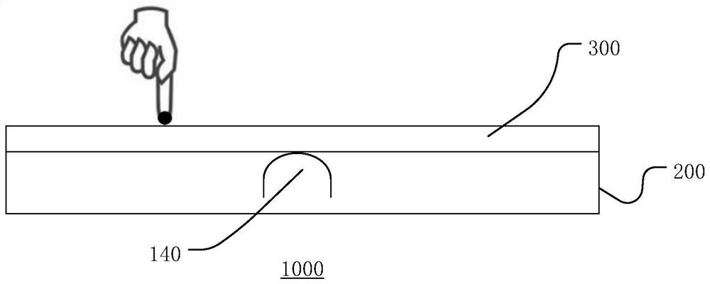
In the existing liquid crystal display 1000, there is a support 140 between the display panel 300 and the backlight module 200. When the pressure on the display panel 300 reaches a certain value, the display panel 300 will be deformed due to the pressure, resulting in uneven brightness. , the current existing test technology is to perform pressure point test by manually pressing the display panel with the operator's fingers. Only relying on the sensory judgment and measurement of the brightness change of the display panel 300, it is impossible to obtain the specific display panel 300 can withstand when the brightness is uniform. The maximum pressure value of
It has also resulted in the inability to optimize the parameter characteristics of the product, which is not conducive to the improvement of product stability and product performance.
Moreover, this parameter of the product is unstable, which will affect the display effect of the display panel 300 to a certain extent.

Method used


Image

  • Display panel testing device and testing method
  • Display panel testing device and testing method
  • Display panel testing device and testing method

Examples


Embodiment Construction

[0035] Various embodiments of the invention will be described in more detail below with reference to the accompanying drawings. In the various drawings, the same elements are denoted by the same or similar reference numerals. For the sake of clarity, various parts in the drawings have not been drawn to scale.

[0036] The specific implementation manners of the present invention will be further described in detail below in conjunction with the accompanying drawings and embodiments.

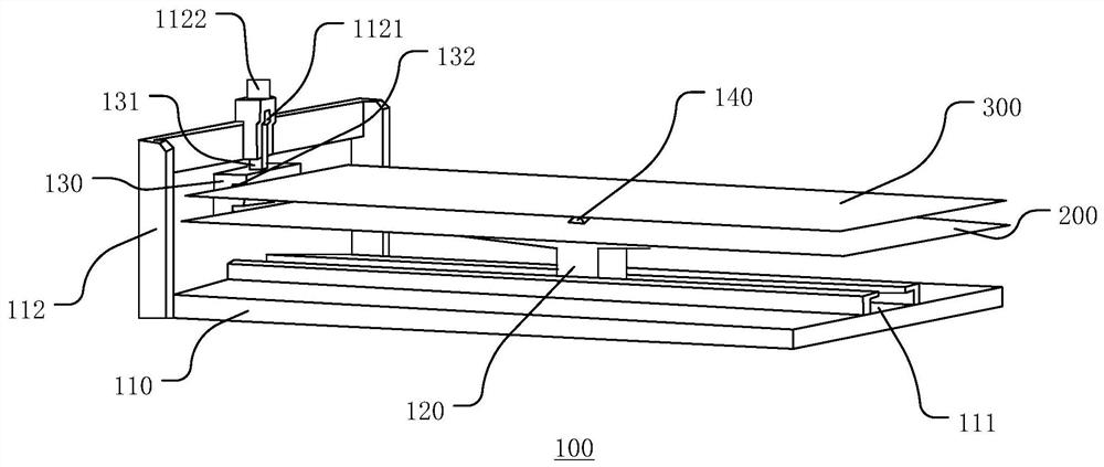
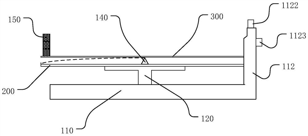
[0037] figure 2 A schematic diagram showing a display panel testing device according to an embodiment of the present invention, image 3 A front view of a display panel testing device according to an embodiment of the present invention is shown. combine Figure 2-Figure 3 As shown, the display panel testing device 100 includes: a base 110 , a carrying platform 120 , a fixing bracket 130 , a support 140 and a force applying device 150 (not shown in the figure). Wherein, the force applying devi...


PUM


Abstract

The present application discloses a display panel testing device and a testing method. The display panel testing device includes: a base; a carrying platform located on the base for carrying a backlight module; a fixing bracket located on one side of the base, It is used to fix one end of the backlight module and the display panel; the support is located between the backlight module and the display panel to provide a fulcrum for the display panel; the backlight module and one end of the display panel are fixed by a fixing bracket , light up the backlight module, place a weight on the other end of the display panel to detect the uneven brightness caused by the pressure of the display panel, measure and quantify the maximum that the display panel can withstand when maintaining uniform brightness Pressure value. To ensure the stability of the brightness of the display panel, this parameter can be further referred to to optimize the design of the display device.

Description

technical field [0001] The invention relates to the technical field of liquid crystal display panel testing, in particular to a display panel testing device and a testing method. Background technique [0002] The existing liquid crystal display (Liquid Crystal Display, LCD) not only has the characteristics of light and thin, small size, but also has the advantages of no radiation, low power consumption and relatively low manufacturing cost. dominate. [0003] Such as figure 1 As shown, the liquid crystal display 1000 mainly includes a display panel 300 and a backlight module 200 located below the display panel 300 . In the existing liquid crystal display 1000, there is a support 140 between the display panel 300 and the backlight module 200. When the pressure on the display panel 300 reaches a certain value, the display panel 300 will be deformed due to the pressure, resulting in uneven brightness. , the current existing test technology is to perform pressure point test b...

Claims


Application Information

Patent Timeline
Patent Type & Authority Patents(China)
IPC IPC(8): G02F1/13
Inventor 赖信杰潘明宏刘春凤王学辉
Owner KUSN INFOVISION OPTOELECTRONICS
Learn More