Supercharge Your Innovation With Domain-Expert AI Agents!

Residue clearing device used after opening and drilling device

A technology of removing device and drilling device, applied in the field of drilling processing, can solve the problem that the residue cannot be taken out

Active Publication Date: 2019-05-28
聊城市博斯麦新材料科技有限公司
View PDF8 Cites 0 Cited by
  • Summary
  • Abstract
  • Description
  • Claims
  • Application Information

AI Technical Summary

Problems solved by technology

[0005] Aiming at the defects in the prior art, the present invention provides a device for removing residues after drilling, so as to solve the problem that the residues after drilling cannot be taken out, reduce the difficulty of drilling, and reduce the processing cost

Method used


Image

  • Residue clearing device used after opening and drilling device
  • Residue clearing device used after opening and drilling device
  • Residue clearing device used after opening and drilling device

Examples


Embodiment 1

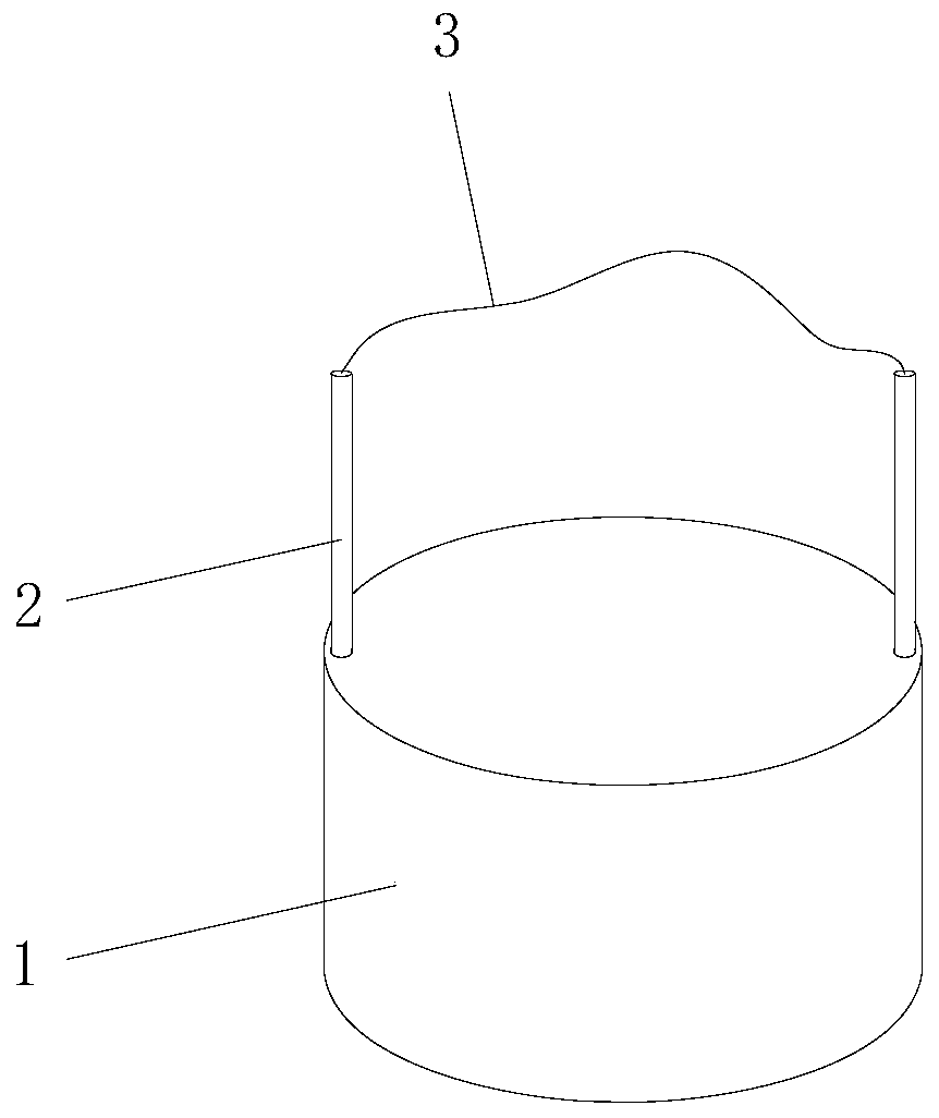
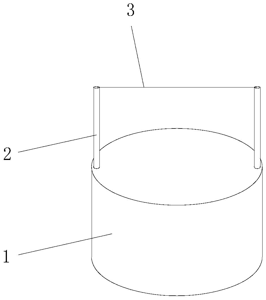
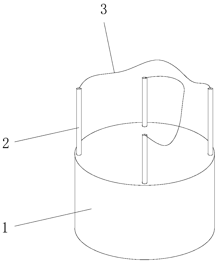
[0049] Such as figure 1 As shown, this embodiment provides a device for removing residues after opening a hole, which includes a base 1, a pipe body 2, a cutting line 3, and a driving mechanism installed in the base 1. The material of the tube body 2 is alloy steel, which has high hardness and strength. In this embodiment, the tube body 2 is provided with an even number, such as figure 1 with image 3 As shown, it can be two, four, six, etc., and the number of pairs of tube bodies 2 is set according to the hardness of the residue to increase the cutting speed and save processing time. This embodiment takes two as examples.

[0050] One end of the two pipes 2 is fixedly connected with one end surface of the base 1 and all the pipes 2 are distributed along the circumference of the base 1. In addition, the lengths of all tube bodies 2 extending from the base 1 are equal, and the angle formed between two opposite tube bodies 2 is 180°. The two ends of the cutting line 3 respectivel...

Embodiment 2

[0062] Such as Picture 8 As shown, this embodiment provides a drilling device, which includes a base 1, a pipe body 2, a cutting line 3, and a driving mechanism installed in the base 1. The serial numbers of the drawings in the second embodiment are the same as those in the first embodiment. One end of all the tube bodies 2 is fixedly connected to the center of one end surface of the base 1, and the end surface is provided with a through hole 18 communicating with the inner cavity of the base 1. The through hole 18 is far away from the tube body 2, and the distance between the through hole 18 and the tube body 2 is the maximum diameter of the opening. The two ends of the cutting line 3 respectively penetrate the base 1 from the pipe body 2 and the through hole 18 and are connected with the driving mechanism.

[0063] The specific structure of the driving mechanism is as follows:

[0064] Such as Picture 11 As shown, the driving mechanism includes a rack 5, a torque sensor 6, a ...


PUM

PropertyMeasurementUnit
angleaaaaaaaaaa

Abstract

The invention discloses a residue clearing device used after opening and a drilling device. The residue clearing device used after opening comprises a base, pipe bodies, a cutting line and a driving mechanism arranged in the base; one ends of the pipe bodies are fixedly connected with one end face of the base, the pipe bodies are distributed in the circumferential direction of the base, the two ends of the cutting line penetrate into the base from one ends of two opposite pipe bodies and are connected with the driving mechanism, through the driving mechanism, the cutting line is kept in the strained state, and the cutting line is pulled to enable the cutting line to be in the moving state. The drilling device comprises the base, the pipe bodies, the cutting line and the driving mechanism in the base. One ends of the pipe bodies are fixedly connected with the center of one end face of the base, the end face is provided with through holes communicating with an inner cavity of the base, and through the driving mechanism, the cutting line is kept in the strained state and the cutting line is pulled to be in the moving state. The problem that residue cannot be taken out after opening can be solved, and the opening difficulty is reduced.

Description

Technical field [0001] The invention relates to the technical field of drilling processing, in particular to a device for removing residues after opening and a drilling device. Background technique [0002] When some processing procedures involve opening holes or opening blind holes in daily life, due to the large diameter of these holes, ordinary drills cannot match such large holes. In this case, the most used tool for opening holes is the hole opener . [0003] But the hole opener only opens a circular hole, and its center will form a cylindrical residue. In most cases, the root of the residue is still connected to the drilled object. Take the cylindrical residue. It will be very difficult to come out, even unable to take out and need to re-open the hole. At present, there is no special device for removing the residue in the hole, so it is difficult to open the hole. [0004] In addition, at present, most of the cases where a drill can be used to make a hole are drilled. Howev...

Claims


Application Information

Patent Timeline
Patent Type & Authority Applications(China)
IPC IPC(8): B23D79/00
Inventor 游晓东
Owner 聊城市博斯麦新材料科技有限公司
Features
  • R&D
  • Intellectual Property
  • Life Sciences
  • Materials
  • Tech Scout
  • Unparalleled Data Quality
  • Higher Quality Content
  • 60% Fewer Hallucinations
Learn More