Adjustable injection mold machining workbench

A technology of injection mold and processing table, which is applied in the field of processing table, can solve problems such as single structure and inability to adjust, and achieve the effect of strong practicability and novel structure

Inactive Publication Date: 2019-05-28
高伟刚
View PDF12 Cites 6 Cited by
  • Summary
  • Abstract
  • Description
  • Claims
  • Application Information

AI Technical Summary

Problems solved by technology

The structure of the processing table used for mold processing in the prior art is relatively simple and cannot be adjusted

Method used


Image

  • Adjustable injection mold machining workbench
  • Adjustable injection mold machining workbench
  • Adjustable injection mold machining workbench

Examples


specific Embodiment approach 1

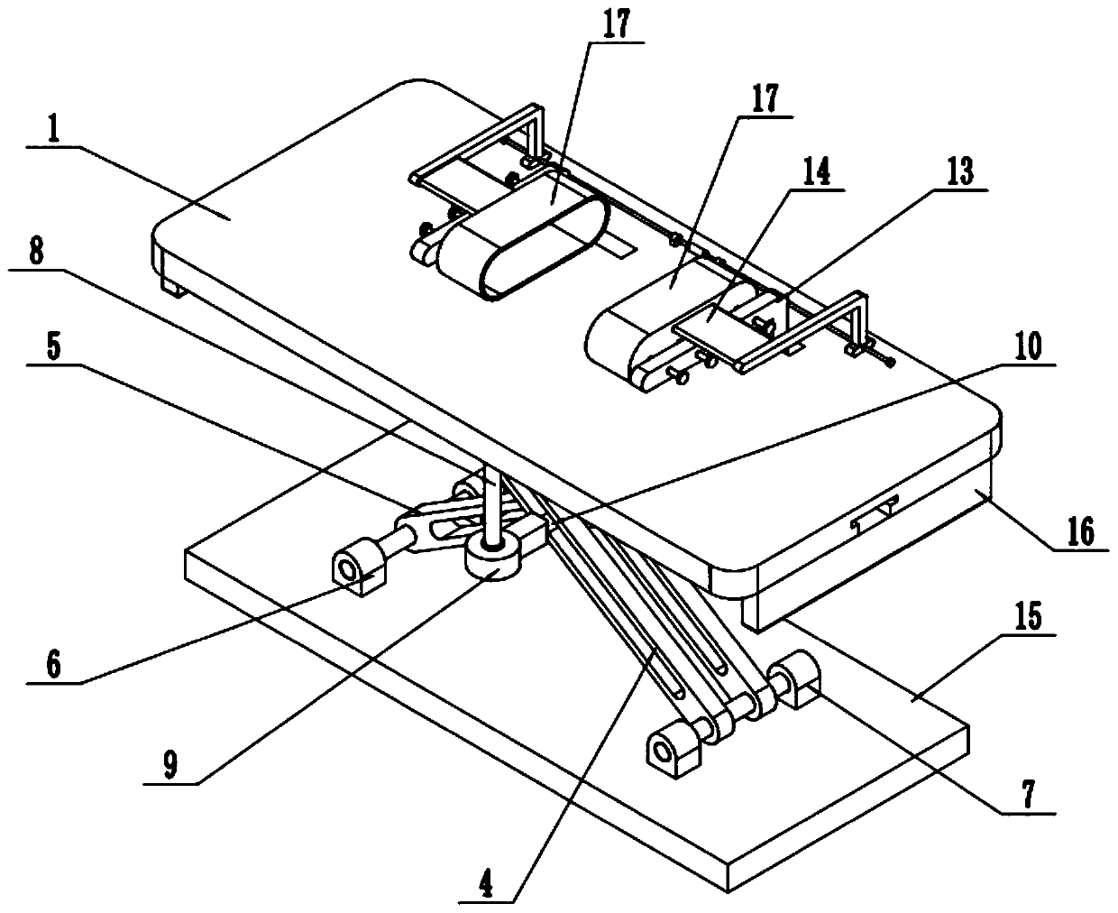
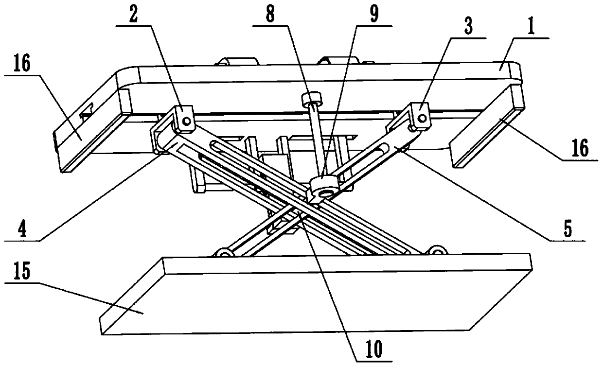
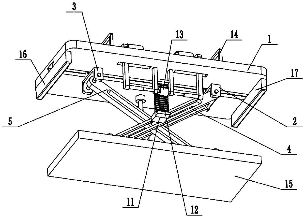
[0028] Such as Figure 1-10 As shown, an adjustable injection mold processing table includes a processing table body 1, a left sliding seat 2, a right sliding seat 3, a left outrigger 4, a right outrigger 5, a left fixing seat 6, a right fixing seat 7, an electric Push rod 8, lifting seat 9, slide bar 10, linkage seat 11, rack 12, mold fixing frame 13, ejector 14 and base plate 15, the middle end of the bottom surface of the processing table body 1 is provided with a T-shaped chute The left sliding seat 2 and the right sliding seat 3 are symmetrically slid and connected to the two ends of the T-shaped chute, and the left sliding seat 2 and the right sliding seat 3 have the same structure; the left fixed seat 6 and the right fixed seat 7 are symmetrical Fixedly connected to the two ends of the top surface of the base plate 15; the two ends of the left support leg 4 are connected to the left sliding seat 2 and the right fixed seat 7 in rotation and fit respectively; the two ends...

specific Embodiment approach 2

[0029] Such as Figure 1-10 As shown, the left and right ends of the bottom surface of the processing table body 1 are respectively fixedly connected with a vertical board, and the two vertical boards are located outside the left sliding seat 2 and the right sliding seat 3 . The setting of the vertical plate is used to prevent the left sliding seat 2 and the right sliding seat 3 from breaking away from the T-shaped chute.

specific Embodiment approach 3

[0030] Such as Figure 1-10 As shown, the top surface of the processing table body 1 is a smooth stainless steel table.


PUM


Abstract

The invention relates to a machining workbench, in particular to an adjustable injection mold machining workbench. The adjustable injection mold machining workbench comprises a machining workbench body, a left sliding base, a right sliding base, a left supporting leg, a right supporting leg, a left fixing base, a right fixing base, an electric pushing rod, a lifting base, a sliding rod, a linkagebase, a rack, a mold fixing frame, ejectors and a base plate; a T-shaped sliding groove is formed in the middle end of the bottom face of the machining workbench body; the left sliding base and the right sliding base are symmetrically connected to the two ends of the interior of the T-shaped sliding groove in a sliding fit mode; and the left fixing base and the right fixing base are symmetricallyand fixedly connected to the two ends of the top face of the base plate. According to the adjustable injection mold machining workbench, two halves of injection molds fixedly installed on the mold fixing frame are buckled or separated by adjusting the height of the machining workbench body, and mold machining work can be conveniently conducted through the injection molds; and in addition, the ejectors capable of achieving adjusting are arranged in the machining workbench, therefore, a mold obtained after injection molding can be ejected out, the structure is novel, and the practicability is high.

Description

technical field [0001] The invention relates to a processing table, in particular to an adjustable injection mold processing table. Background technique [0002] Injection mold is a tool for producing plastic products; it is also a tool for giving plastic products complete structure and precise dimensions. Injection molding is a processing method used in the mass production of certain complex-shaped parts. Specifically, it refers to injecting the heated and melted plastic into the mold cavity under high pressure from the injection molding machine, and after cooling and solidifying, a molded product is obtained. The structure of the processing table used for mold processing in the prior art is relatively simple and cannot be adjusted. Contents of the invention [0003] The purpose of the present invention is to provide an adjustable injection mold processing table, which can buckle or separate the two halves of the injection mold fixedly installed on the mold fixing frame...

Claims


Application Information

Patent Timeline
Patent Type & Authority Applications(China)
IPC IPC(8): B29C45/17B29C45/40B29C45/66
Inventor 不公告发明人
Owner 高伟刚
Why Eureka
Try Eureka