
Finished automobile pipeline connecting tool and working method thereof

A pipeline and tooling technology, which is applied in the field of vehicle pipeline connection tooling, can solve problems such as easy shaking in processing, unstable devices, shaking, etc., and achieve the effects of facilitating timely processing, improving work efficiency, and avoiding shaking

Pending Publication Date: 2019-11-22
ANHUI ANKAI AUTOMOBILE
View PDF1 Cites 2 Cited by
  • Summary
  • Abstract
  • Description
  • Claims
  • Application Information

AI Technical Summary

Problems solved by technology

[0004] The purpose of the present invention is to provide a vehicle pipeline connection tool to solve the problem that the angle of the support rod used in the existing connection tool cannot be adjusted. Most of the support rods are fixed on the bottom plate by welding. When the pipeline is fixed, it cannot be used, so that after the pipeline is fixed, it is easy to shake during processing; when the existing pipeline connection tool is fixed with a curved pipeline, the pressure plate cannot be connected with the tube because the nozzle is tilted or bent down. contact with the mouth, resulting in the instability of the whole device after the connection, shaking during pipeline processing, which affects the processing quality; the existing connection tooling, when processing the connection of two pipelines, mostly uses the connection to be fixed. In this way, it is necessary to complete the processing of the entire connection to disassemble the tooling and expose the connection, so that the unreasonable processing of the connection cannot be found in time, and it needs to be reworked, which delays time.

Method used


Image

  • Finished automobile pipeline connecting tool and working method thereof
  • Finished automobile pipeline connecting tool and working method thereof
  • Finished automobile pipeline connecting tool and working method thereof

Examples


Embodiment Construction

[0030] The technical solutions of the present invention will be clearly and completely described below in conjunction with the embodiments. Apparently, the described embodiments are only some of the embodiments of the present invention, not all of them. Based on the embodiments of the present invention, all other embodiments obtained by persons of ordinary skill in the art without creative efforts fall within the protection scope of the present invention.

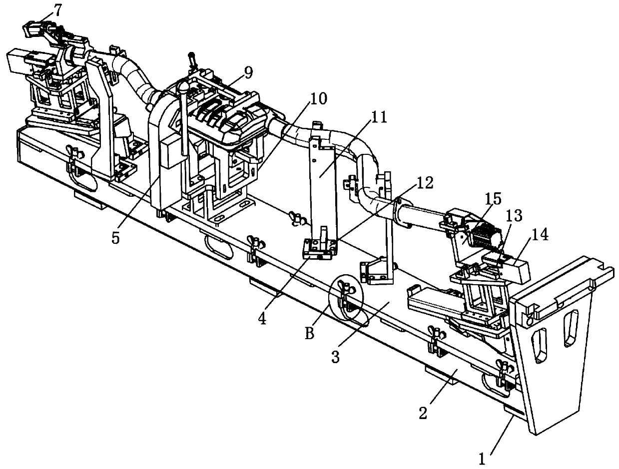
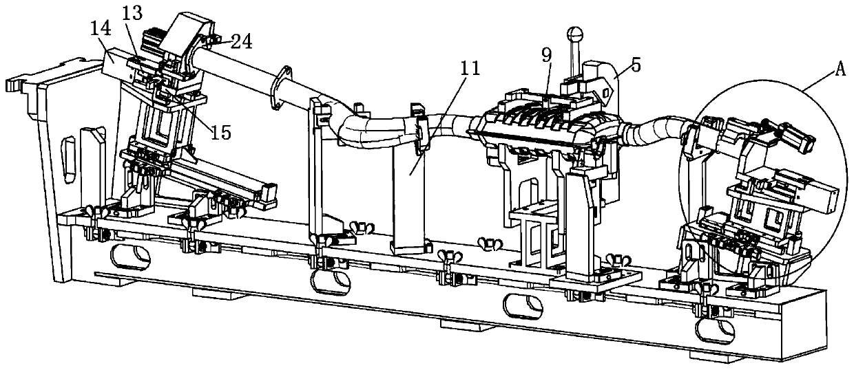
[0031] Such as Figure 1-5 As shown, a vehicle pipeline connection tool includes a base 2, a base plate 3 and a support rod 11, the top of the base 2 is provided with a base plate 3, and two rows of card slots are symmetrically arranged on both sides of the base plate 3, each Two clamping blocks 22 are arranged on the side wall of the base 2 below the two draw-in slots, and a rotating shaft 23 is arranged between the two clamping blocks 22. The clamping blocks 22 are rotatably connected, and a screw rod 21 is fixedly arrange...


PUM


Abstract

The invention discloses a finished automobile pipeline connecting tool. The finished automobile pipeline connecting tool comprises a pedestal, a base plate and a supporting rod; the base plate is arranged at the top of the pedestal; the edges of the two sides of the base plate are symmetrically provided with two rows of clamping slots; the part, positioned below each clamping slot, of the sidewallof the pedestal is provided with two clamping blocks; between every two clamping blocks is provided with a rotating shaft; the two ends of each rotating shaft are correspondingly arranged on the twocorresponding clamping blocks and are rotationally connected with the two clamping blocks; a first hydraulic cylinder is used for controlling a first hydraulic rod therein to move toward the outer side of the cylinder body so that the first hydraulic rod can push the top end of a supporting plate to move, thus a pressing disc moves down to tightly press the opening of a pipeline and fix the position of the pipeline; when the opening of the pipeline is warped, the first hydraulic cylinder is used for controlling the first hydraulic rod therein to move toward the inner side of the cylinder bodyso that the pressing disc moves upwards to make sure that the pipeline makes contact with the pressing disc and the position of the pipeline is fixed; shake of the pipeline is prevented when the pipeline is processed; and thus the processing quality is not affected.

Description

technical field [0001] The invention relates to the field of vehicle pipeline tooling equipment, in particular to a vehicle pipeline connection tool and a working method thereof. Background technique [0002] At present, various fixtures and fixtures are required when the pipelines of the whole vehicle are being processed. When the two pipelines are combined together, a connecting tool is required. The support rod used in the existing pipeline connecting tool cannot be adjusted in angle. Most of the support rods are fixed on the bottom plate by welding. When some curved pipelines need to be supported, they cannot be used, so that after the pipelines are fixed, they are prone to shaking during processing; the existing pipeline connection tooling encounters curved pipelines When fixing, because the nozzle is tilted or bent down, the pressure plate cannot be in contact with the nozzle, resulting in the instability of the whole device after connection, and the pipeline will shak...

Claims


Application Information

Patent Timeline
Patent Type & Authority Applications(China)
IPC IPC(8): B23Q3/06
CPCB23Q3/062
Inventor 黄叶明张辉包宝葛飞
Owner ANHUI ANKAI AUTOMOBILE
Learn More