
A kind of storage battery component and automobile

A battery and component technology, applied in vehicle components, circuits or fluid pipelines, transportation and packaging, etc., can solve problems such as narrow engine compartment space, battery leakage, and increase in batteries, etc., to achieve simple installation and operation, save space, improve The effect of stability

Active Publication Date: 2020-11-03
GEELY AUTOMOBILE INST NINGBO CO LTD +1
View PDF12 Cites 0 Cited by
  • Summary
  • Abstract
  • Description
  • Claims
  • Application Information

AI Technical Summary

Problems solved by technology

[0003] The reliability and firmness of the battery fixing method directly affect the service life of the battery. The space in the engine compartment of the vehicle is small. In order to prevent the temperature from being too high and prolong the life of the battery, the battery is installed in the trunk of the vehicle; in some traffic accidents and safety collision test simulations The battery in the engine compartment still has 5% slipping and falling off during high-speed collisions; these phenomena may cause battery leakage, short circuit, open circuit and personal injury; therefore, increasing the firmness of the battery installation is a problem that needs to be solved urgently

Method used


Image

  • A kind of storage battery component and automobile
  • A kind of storage battery component and automobile
  • A kind of storage battery component and automobile

Examples


Embodiment 1

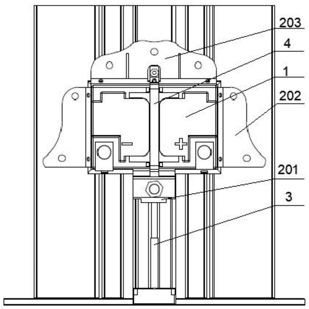
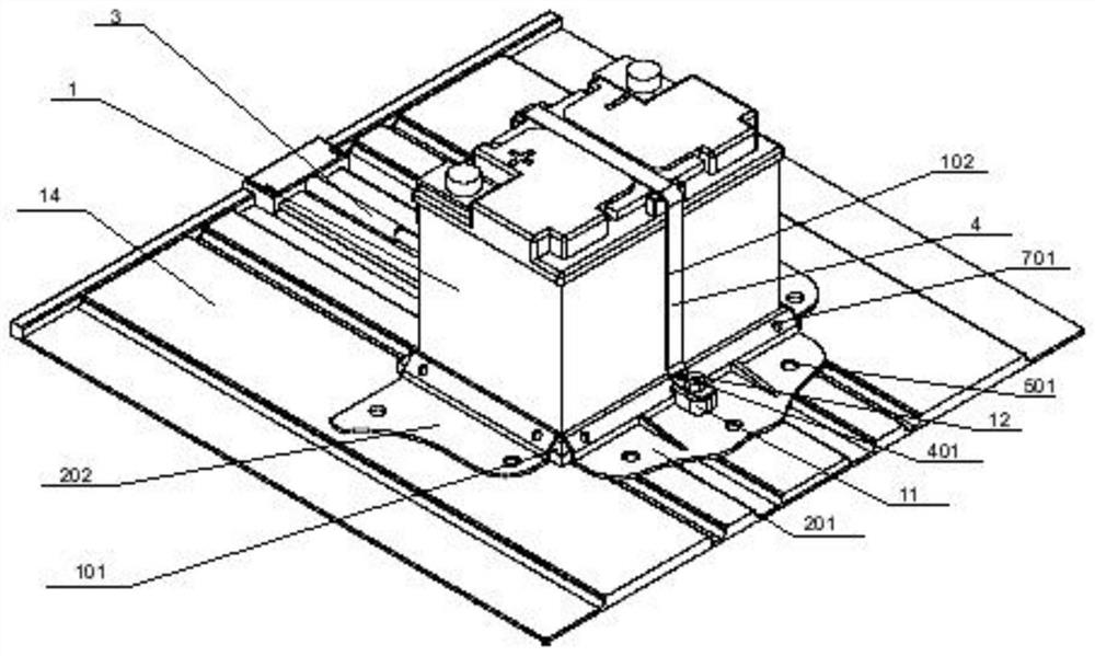
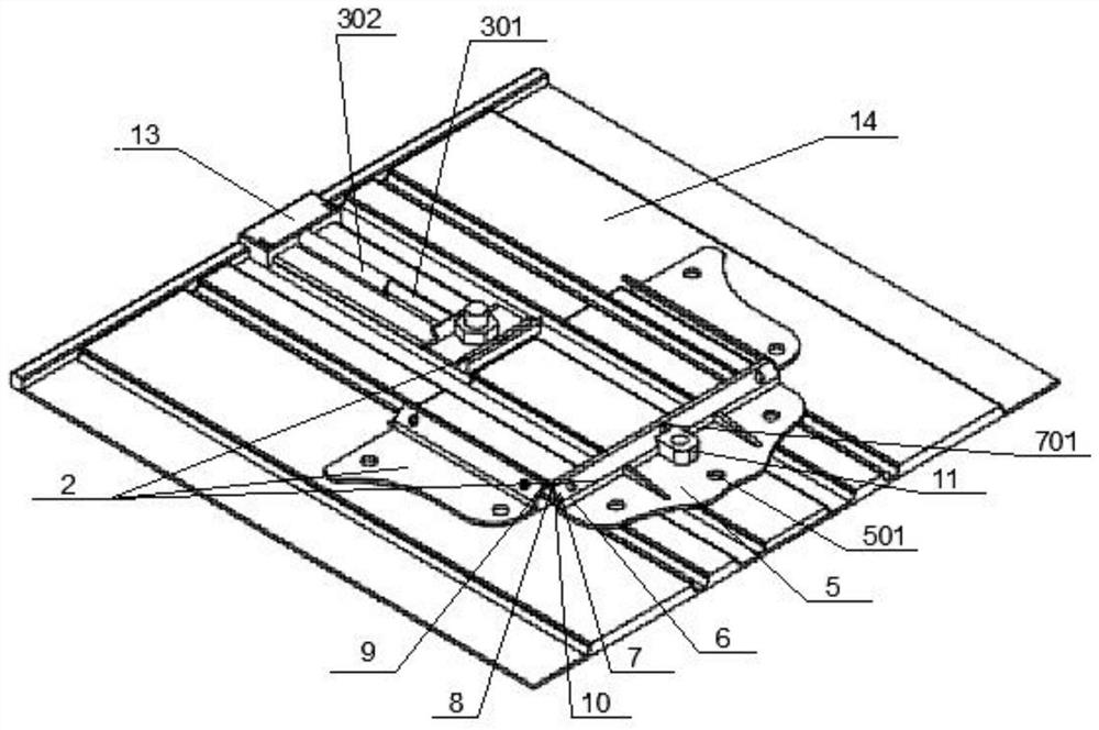
[0033] Such as Figure 1 to Figure 3 Shown: a battery assembly, including a battery 1, a battery chassis support 2, a mechanical pressure bar 3 and a fixing belt 4;

[0034] The battery chassis support 2 includes a first support 201, a second support 202 and a third support 203, and the first support 201, the second support 202 and the third support 203 are all used to fix the battery 1;

[0035] The mechanical pressure rod 3 is fixedly connected to the end of the first bracket 201 away from the battery 1 , and the mechanical pressure rod 3 is used to push the first bracket 201 along the connection direction between the first bracket 201 and the battery 1 exercise;

[0036] One end of the fixing belt 4 is fixedly connected to the first bracket 201, and the other end is detachably connected to the third bracket 203;

[0037] The side wall of the storage battery 1 is provided with a wall groove 102 matched with the fixing belt 4, and the wall groove 102 is used to accommodate...

Embodiment 2

[0042] Embodiment 2: be the preferred embodiment of embodiment 1

[0043] Such as Figure 1 to Figure 3 Shown: a battery assembly, including battery 1, battery chassis support 2, mechanical pressure bar 3 and fixing belt 4;

[0044] The battery chassis support 2 includes a first support 201, a second support 202 and a third support 203, and the first support 201, the second support 202 and the third support 203 are all used to fix the battery 1;

[0045] The mechanical pressure rod 3 is fixedly connected to the end of the first bracket 201 away from the battery 1 , and the mechanical pressure rod 3 is used to push the first bracket 201 along the connection direction between the first bracket 201 and the battery 1 exercise;

[0046] One end of the fixing belt 4 is fixedly connected to the first bracket 201, and the other end is detachably connected to the third bracket 203;

[0047] The side wall of the storage battery 1 is provided with a wall groove 102 matched with the f...

Embodiment 3

[0063] Embodiment 3: be the preferred embodiment of embodiment 2

[0064] The difference with embodiment 2 is:

[0065] The third bracket 203 is further provided with at least one reinforcing rib, which can strengthen the rigidity of the third bracket 203 and securely fasten the fixing belt on the connecting block 11 .

[0066] Such as figure 2 As shown, there are two transition blocks on the top of the battery 1 away from the battery base 101, and the transition blocks are respectively provided with notches that engage with the fixing belt 4, which can strengthen the fixing belt 4 and the upper wall groove 102 on the side wall of the battery 1. closeness of contact.

[0067] Further preferably, the fixing belt 4 is a belt.


PUM


Abstract

The invention discloses a storage battery assembly which comprises a storage battery, a storage battery chassis bracket, a mechanical pressure bar and a fixed strip. The storage battery chassis bracket comprises a first bracket, a second bracket and a third bracket for fixing the storage battery; the mechanical pressure bar is fixedly connected to the end, far away from the storage battery, of thefirst bracket, and is used for pushing the first bracket to move upward in the connecting direction of the first bracket and the storage battery; one end of the fixed strip is fixedly connected to the first bracket while the other end of the fixed strip is detachably connected to the third bracket; a wall slot matched with the fixed strip is formed in the side wall of the storage battery for accommodating the fixed strip. The invention also discloses an automobile which comprises the storage battery assembly and an automobile body. The storage battery assembly is arranged on a bottom plate ofthe automobile body. The storage battery is mounted and fixed by a way of triple-fixation by the storage battery chassis bracket, the mechanical pressure bar and the fixed strip, so that the fastnessof the storage battery is improved. The storage battery assembly is simple and quick to operate, convenient to detach and higher in fastness.

Description

technical field [0001] The invention relates to the technical field of accumulators, in particular to an accumulator assembly and an automobile. Background technique [0002] The battery is the energy center of the automotive electrical equipment. Its function is to supply the engine with electricity. When the vehicle is ready to start, the battery will discharge to provide power to the starter, and the starter will drive the flywheel and crankshaft to start the vehicle. If the engine power supply is insufficient Or provide power for electrical appliances in the car such as audio system, lighting system, etc. when it is not started. When the engine starts to supply power normally, the battery will collect and store electrical energy for future use. [0003] The reliability and firmness of the battery fixing method directly affect the service life of the battery. The space in the engine compartment of the vehicle is small. In order to prevent the temperature from being too hi...

Claims


Application Information

Patent Timeline
Patent Type & Authority Patents(China)
IPC IPC(8): B60R16/033
Inventor 赵凯龙李月明习波波
Owner GEELY AUTOMOBILE INST NINGBO CO LTD
Learn More