Flying wing combined control surface with high maneuvering characteristic

A technology of maneuverability and combined rudders, applied in the field of flying wing combined rudder surfaces, can solve the problems of flying wing layout aircraft that are difficult to achieve high maneuverability, negative lift offsetting the whole aircraft, and low efficiency of rudder surfaces, so as to increase the available angle of attack range effect

Inactive Publication Date: 2019-05-28
CHENGDU AIRCRAFT INDUSTRY GROUP
View PDF12 Cites 1 Cited by
  • Summary
  • Abstract
  • Description
  • Claims
  • Application Information

AI Technical Summary

Problems solved by technology

However, the flying wing layout aircraft has no tail, the rudder surface controlling the pitch is short in moment arm, and the rudder surface efficiency is low. During high maneuvering flight, it is difficult for the rudder surface to effective

Method used


Image

  • Flying wing combined control surface with high maneuvering characteristic
  • Flying wing combined control surface with high maneuvering characteristic
  • Flying wing combined control surface with high maneuvering characteristic

Examples


Embodiment 1

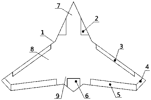
[0026] Such as figure 1 Shown, a kind of flying-wing combined rudder surface with high maneuverability characteristic comprises fuselage 1, and described fuselage 1 comprises nose 7, wing 8 and tail 9, and described wing 8 is two, and symmetrical It is arranged on both sides of the fuselage 1, the two sides of the nose 7 are provided with side strip wings 2, and the side strip wings 2 are axially connected with the nose 7 through the rotating shaft 10, and the upper end of the wing 8 is provided with The leading edge flap 3 is provided with a rudder surface 4 at the side end, and the lower end is provided with an elevon 5, and the leading edge flap 3, the rudder surface 4 and the elevon 5 are dynamically connected with the wing 8 through a rotating shaft 10, so that The tail 9 is provided with a gas rudder 6, and the gas rudder 6 is dynamically connected with the tail 9 through a rotating shaft 10.

[0027] The combined flying wing has a length of 20m, a height of 3.5m, and a...

Embodiment 2

[0029] Such as figure 1 Shown, a kind of flying-wing combined rudder surface with high maneuverability characteristic comprises fuselage 1, and described fuselage 1 comprises nose 7, wing 8 and tail 9, and described wing 8 is two, and symmetrical It is arranged on both sides of the fuselage 1, the two sides of the nose 7 are provided with side strip wings 2, and the side strip wings 2 are axially connected with the nose 7 through the rotating shaft 10, and the upper end of the wing 8 is provided with The leading edge flap 3 is provided with a rudder surface 4 at the side end, and the lower end is provided with an elevon 5, and the leading edge flap 3, the rudder surface 4 and the elevon 5 are dynamically connected with the wing 8 through a rotating shaft 10, so that The tail 9 is provided with a gas rudder 6, and the gas rudder 6 is dynamically connected with the tail 9 through a rotating shaft 10.

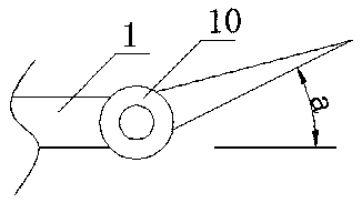
[0030] Such as figure 2 As shown, the side strip wing 2, the leading edge ...

Embodiment 3

[0036] Such as figure 1 Shown, a kind of flying-wing combined rudder surface with high maneuverability characteristic comprises fuselage 1, and described fuselage 1 comprises nose 7, wing 8 and tail 9, and described wing 8 is two, and symmetrical It is arranged on both sides of the fuselage 1, the two sides of the nose 7 are provided with side strip wings 2, and the side strip wings 2 are axially connected with the nose 7 through the rotating shaft 10, and the upper end of the wing 8 is provided with The leading edge flap 3 is provided with a rudder surface 4 at the side end, and the lower end is provided with an elevon 5, and the leading edge flap 3, the rudder surface 4 and the elevon 5 are dynamically connected with the wing 8 through a rotating shaft 10, so that The tail 9 is provided with a gas rudder 6, and the gas rudder 6 is dynamically connected with the tail 9 through a rotating shaft 10.

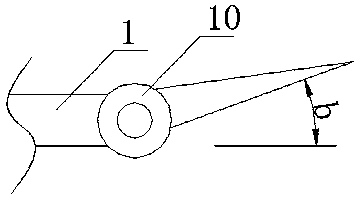
[0037] Such as figure 2As shown, the side strip wing 2, the leading edge f...


PUM

PropertyMeasurementUnit
Lengthaaaaaaaaaa
Lengthaaaaaaaaaa

Abstract

The invention discloses a flying wing combined control surface with the high maneuvering characteristic. The flying wing combined control surface comprises a fuselage, wherein the fuselage comprises ahead, wings and a tail; the two wings are symmetrically arranged on two sides of the fuselage; strake wings are arranged on two sides of the head and in shaft driving connection with the head througha rotating shaft; a leading edge flap is arranged at the upper end of each wing, a control surface is arranged at the side end, an elevon is arranged at the lower end, and the leading edge flap, thecontrol surface and the elevon are in shaft driving connection with the wing through the rotating shaft; a jet vane is arranged on the tail and in shaft driving connection with the tail through the rotating shaft. By reasonably arranging the control surfaces and control combination of the control surfaces, the demand of high maneuvering flight of flying wings for pitch moment and the demand for low resistance during conventional level flight are both taken into account, and high maneuvering flight is easy to realize in engineering.

Description

technical field [0001] The application belongs to the field of aircraft design, and in particular relates to a flying-wing combined rudder surface with high maneuverability. Background technique [0002] The main feature of flying wing is that there is no tail, and main wing adds fuselage to constitute whole body (flying wing machine), and what the first aircraft in the world adopts is exactly this form. The United States and Germany began to study flying wing aircraft almost at the same time, and Germany developed and produced the Holden H0229 (the test aircraft production stage ended after World War II). [0003] The patent number is CN201520968560.6, and the application date is 2015-11-30. It discloses a combined four-axis flying wing aircraft, which is characterized in that it includes a central column fuselage, and the left and right settings are symmetrically arranged on the central column fuselage. The two wings of the two wings, the ribs of the two wings are provide...

Claims


Application Information

Patent Timeline
IPC IPC(8): B64C9/00B64C39/10
Inventor 冯文梁许云飞
Owner CHENGDU AIRCRAFT INDUSTRY GROUP
Why Eureka
Try Eureka