Rudder control type vertical take-off and landing unmanned aerial vehicle and take-off and landing control method thereof

A technology for vertical take-off and landing of unmanned aerial vehicles, applied in the field of aircraft, which can solve problems such as complex control strategies, small flight range, and obvious jitter during take-off and landing, and achieve improved cruise energy conversion efficiency, smooth and flexible flight control, and simple control methods effective effect

Pending Publication Date: 2021-02-02
CAIHONG DRONE TECH CO LTD +1
View PDF0 Cites 2 Cited by
  • Summary
  • Abstract
  • Description
  • Claims
  • Application Information

AI Technical Summary

Problems solved by technology

[0004] The UAV that adopts the rudder control method to take off and land vertically is Google's Project wing. Project wing is a small UAV that uses a rudder control method in the form of a flying wing layout to achieve vertical takeoff and landing. The steering rudder surface is the end of the main wing. The flaperon and dual-purpose rudder surface make the control strategy of this model more complicated, and the vibration is obvious during the take-off and landing phase
Tilting-rotor UAVs have appeared domestically and internationally in recent years. This configuration pays a large weight cost for the tilting mechanism for vertical take-off and landing, and its control strategy is also relatively complicated, which is prone to accidents during the take-off and landing phase.
The low cruising efficiency and small range of multi-rotor UAVs are also significant defects.

Method used


Image

  • Rudder control type vertical take-off and landing unmanned aerial vehicle and take-off and landing control method thereof
  • Rudder control type vertical take-off and landing unmanned aerial vehicle and take-off and landing control method thereof
  • Rudder control type vertical take-off and landing unmanned aerial vehicle and take-off and landing control method thereof

Examples


Embodiment Construction

[0043] The following describes the present invention in detail, and the features and advantages of the present invention will become more clear and definite along with these descriptions.

[0044] The word "exemplary" is used exclusively herein to mean "serving as an example, embodiment, or illustration." Any embodiment described herein as "exemplary" is not necessarily to be construed as superior or better than other embodiments. While various aspects of the embodiments are shown in drawings, the drawings are not necessarily drawn to scale unless specifically indicated.

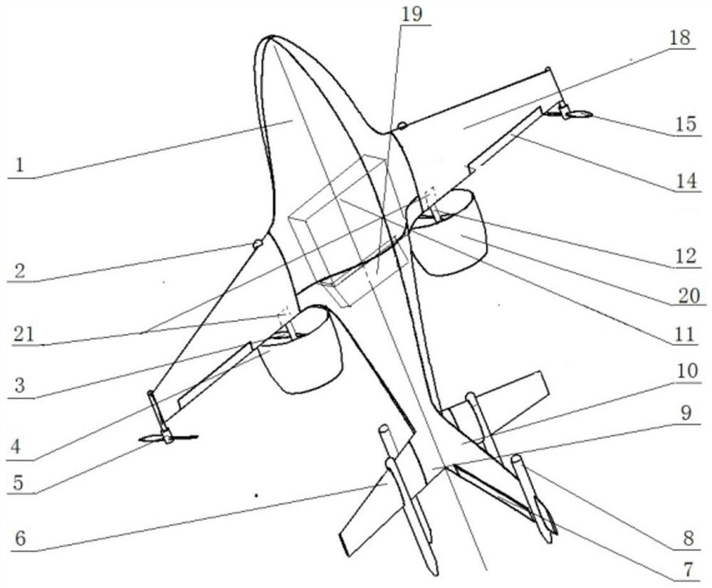
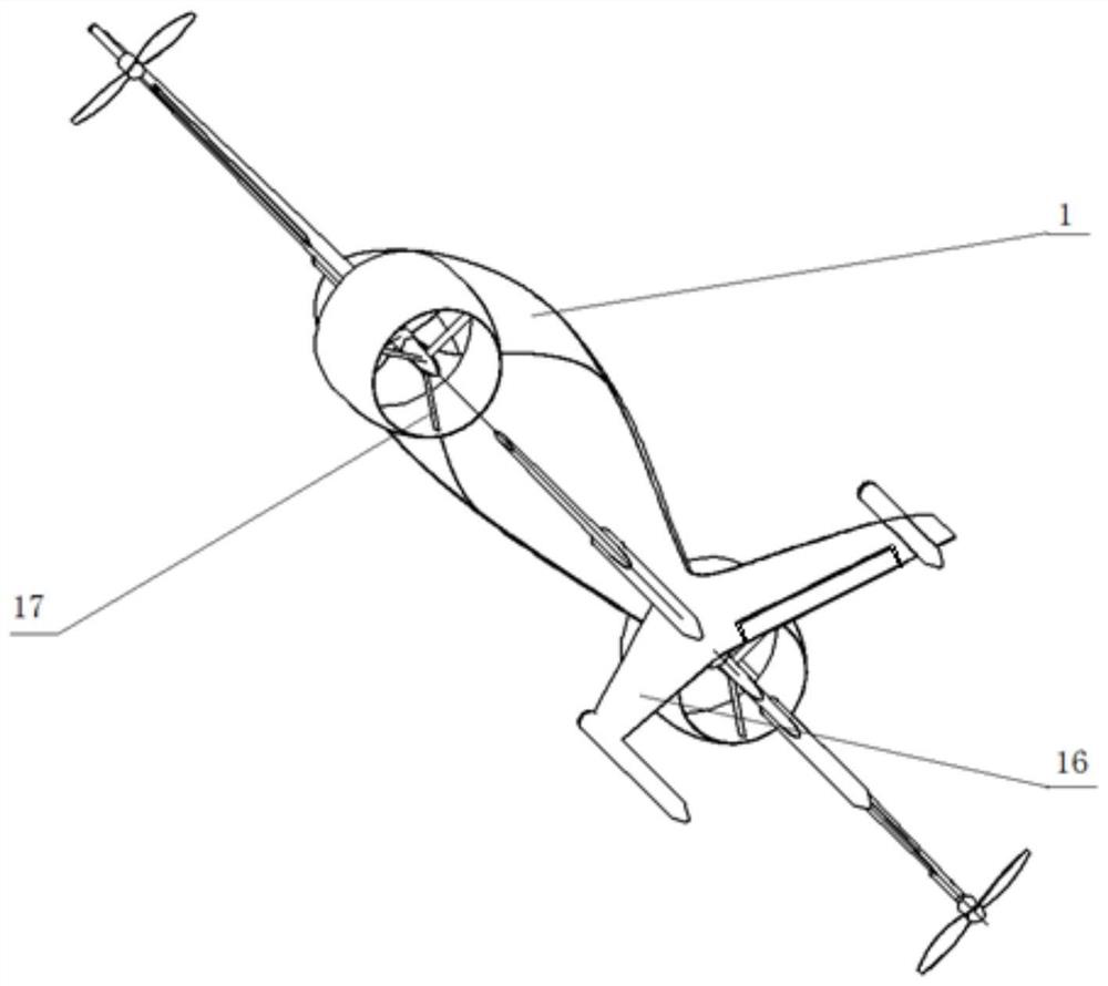
[0045]The invention provides a rudder-controlled vertical take-off and landing unmanned aerial vehicle, such as figure 1 with figure 2 , where 1 is the body, 2 is the shaft support rod, 3 is the propeller, 4 is the main power propeller, 5 is the auxiliary power propeller motor, 6 is the movable part of the horizontal tail, 7 is the rudder, 8 is the landing bracket, 9 is the horizontal tail, 10 is the upp...


PUM


Abstract

The invention provides a rudder control type vertical take-off and landing unmanned aerial vehicle and a take-off and landing control method thereof. Symmetric horizontal tails, upper vertical tails,lower vertical tails and take-off and landing supporting rods are arranged at the slender tail of a rudder control type vertical take-off and landing unmanned aerial vehicle body; a pair of fixed mainpower propellers, a pair of auxiliary power propellers and corresponding independent motors are installed on the root portion and the wing tip of the rear edge of the main wing respectively. The rudder control type fixed wing vertical take-off and landing technology is adopted, the unmanned aerial vehicle can take off vertically and cruise horizontally through the fixed wings, the take-off and landing device is simple in structure, the flight mode conversion mode is convenient, and complex tilting mechanisms of existing other forms of vertical take-off and landing aircrafts or power devices which are not fully utilized are removed. The operation is flexible, and the flight mode conversion cost is low. By utilizing the wake flow and the full-motion horizontal tail of the main propulsion ducted propeller, the horizontal tail is deflected after the aircraft vertically rises to a certain height, so that the aircraft is smoothly transited to a horizontal cruise state.

Description

technical field [0001] The invention belongs to the field of aircraft, and in particular relates to a rudder-controlled vertical take-off and landing unmanned aerial vehicle and a take-off and landing control method thereof. Background technique [0002] Compared with horizontal take-off and landing UAVs, vertical take-off and landing UAVs have the characteristics of flexible take-off and landing, and are less affected by the environment and site. Although pure rotor UAVs can take off and land vertically, their cruising efficiency is lower than that of fixed-wing aircraft. Therefore, fixed-wing UAVs with vertical take-off and landing capabilities have inherent advantages in cruising efficiency and site adaptability. There are many applications in short-distance cargo delivery, vaccine delivery and other fields. [0003] The existing layout forms of fixed-wing UAVs with vertical take-off and landing capabilities include tilt-rotor UAVs, tilting ducted propellers, thrust-vect...

Claims


Application Information

Patent Timeline
Patent Type & Authority Applications(China)
IPC IPC(8): B64C27/28B64C29/02B64C5/02B64C25/04
CPCB64C27/28B64C29/02B64C5/02B64C25/04B64U70/80B64U10/25B64U30/20B64U70/00
Inventor 崔跃理王超许敏吕超朱振宇刘凯飞葛春雷
Owner CAIHONG DRONE TECH CO LTD
Why Eureka
Try Eureka