
A distributed propulsion flying wing aircraft

A distributed and aircraft technology, applied in the field of aircraft, can solve the problems of insufficient infrared stealth performance and high fuel consumption, and achieve good infrared stealth performance, low speed, and weak jet noise

Active Publication Date: 2021-07-20
INST OF HIGH SPEED AERODYNAMICS OF CHINA AERODYNAMICS RES & DEV CENT
View PDF8 Cites 0 Cited by
  • Summary
  • Abstract
  • Description
  • Claims
  • Application Information

AI Technical Summary

Problems solved by technology

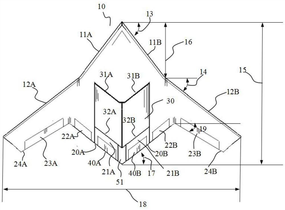
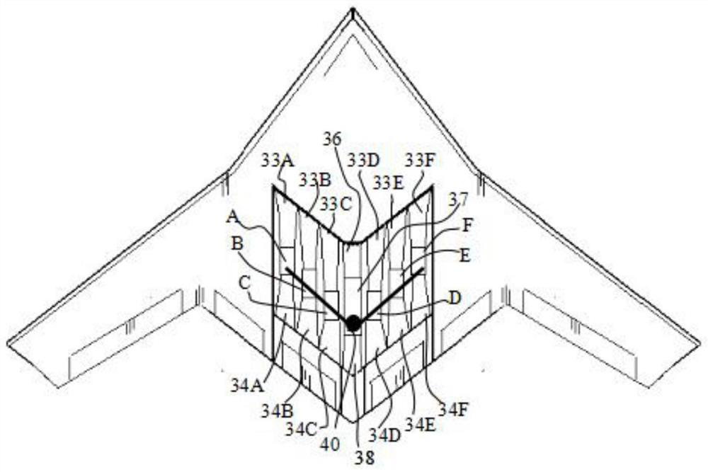
[0008] The purpose of the present invention is to provide a distributed propulsion flying wing aircraft, which aims to solve the technical problems of high fuel consumption, insufficient infrared stealth performance, and pitch control in the prior art

Method used


Image

  • A distributed propulsion flying wing aircraft
  • A distributed propulsion flying wing aircraft
  • A distributed propulsion flying wing aircraft

Examples


Embodiment Construction

[0031] Embodiments of the present invention will be described in detail below, and examples of the embodiments are illustrated in the drawings, in which the same or similar reference numerals represent the same or similar elements or elements having the same or similar functions. The following is exemplary, and is intended to be used to illustrate the invention without understanding the limitation of the invention.

[0032] In the description of the present invention, it is to be noted that when the element is referred to as "fixed to" or "set to" another element, it can be directly on the other element or indirectly on the other element. When one element is called "connected to" another element, it can be directly connected to another element or indirectly connected to the other element.

[0033] It is to be understood that the term "length", "width", "upper", "lower", "front", "post", "right", "vertical", "level", "top" The orientation or position relationship of "bottom" "insid...


PUM


Abstract

The present invention is applicable to the field of aircraft technology, and provides a distributed propulsion flying wing aircraft, comprising a flying wing body and a distributed propulsion system, the distributed propulsion system is arranged inside the flying wing body, and the distributed propulsion The system includes a ducted fan system, a turbine engine system, and a shaft power transfer system, and the shaft power transfer system transfers shaft power output by the turbine engine system to the ducted fan system. The distributed propulsion system in the invention integrates the ducted fan system and the turbine engine system, which achieves the effect of a large bypass ratio engine and reduces the fuel consumption rate of the flying-wing aircraft by more than 25%.

Description

Technical field [0001] The present invention belongs to the field of aircraft, and in particular, the present invention relates to a distributed propulsion flying aircraft. Background technique [0002] Flying Wing Aircraft takes into account good aerodynamic performance and stealth performance, which has a long history of development. There are not many existing technologies involving the flying wing aircraft. In 2012, it is disclosed in the 2012 US8191820B1, which is characterized in that the flying wing, a duck wing, a high pressure air distribution system, which mainly solves the takeoff Insufficient strength, pitch manipulation control, and other technical issues. However, the flying wing aircraft in this patent uses a routine turbofan engine, and the fuel consumption rate indicator is not significantly improved. It can only rely on large carrier oil to achieve voyage, long-distance flight, and infrared stealth performance is not significantly improved. . Therefore, the flyi...

Claims


Application Information

Patent Timeline
Patent Type & Authority Patents(China)
IPC IPC(8): B64C27/20B64D27/12
CPCB64C27/20B64D27/12
Inventor 达兴亚马晓永唐世勇樊建超李方吉赵清李阳
Owner INST OF HIGH SPEED AERODYNAMICS OF CHINA AERODYNAMICS RES & DEV CENT
Learn More