
Airfoil having a movable control surface

a control surface and airfoil technology, applied in the field of airfoil flaps, can solve the problems of large changes in the location of the airfoil center of lift, aircraft to experience large nose-down pitching moment, reduce the overall lift available, etc., to achieve small lift penalties, enhance the ability of invention, and increase the pitching moment

Inactive Publication Date: 2007-12-20
LOCKHEED MARTIN CORP
View PDF6 Cites 10 Cited by
  • Summary
  • Abstract
  • Description
  • Claims
  • Application Information

AI Technical Summary

Benefits of technology

[0011] An advantage of the present invention is that the present invention does not induce large pitching moments and therefore can be employed on an aircraft with a much smaller conventional elevator surface at the rear of the plane. Additionally, the present invention allows for much smaller lift penalties due to pitch axis trimming. A smaller elevator further enhances the ability of the invention to operate at transonic speeds, where a smaller elevator induces substantially less drag than the larger elevator surfaces typically required for the other high-lift prior art flap systems. Another advantage of the present invention optionally includes the ability for an aircraft employed with the present invention to reverse its thrust, which can greatly improve the aircraft's landing and taxing abilities. The present invention can greatly improve thrust reversing efficiencies and significantly reduce lift in landing operations. Reduced lift on the wing after touchdown and during landing rollout causes more of the aircraft weight to be supported by the aircraft landing gear, thereby allowing aircraft brakes to be more forcefully applied without skidding, and high thrust reversing efficiency provides large thrust reversing forces to slow the aircraft.

Problems solved by technology

While these prior art flaps, or modifications thereof, generally provide large modulation of airfoil lift and drag, they also can induce large changes in the location of the airfoil center-of-lift.
Typically, when these prior art flaps are deployed, especially in the case of the Fowler and slotted flaps, the large changes in the airfoil center-of-lift can cause the aircraft to experience large nose-down pitching moment.
Therefore, these prior art flaps require large and / or all-moving elevator surfaces at the rear of the aircraft to provide rear-downward forces for aircraft pitch trimming.
Additionally, these rear-downward elevator forces reduce the overall lift available to the keep the aircraft airborne.

Method used


Image

  • Airfoil having a movable control surface
  • Airfoil having a movable control surface
  • Airfoil having a movable control surface

Examples


Embodiment Construction

[0031] The present invention may be understood more readily by reference to the following detailed description of the invention taken in connection with the accompanying drawing figures, which form a part of this disclosure. It is to be understood that this invention is not limited to the specific devices, methods, conditions or parameters described and / or shown herein, and that the terminology used herein is for the purpose of describing particular embodiments by way of example only and is not intended to be limiting of the claimed invention. Also, as used in the specification including the appended claims, the singular forms “a,”“an,” and “the” include the plural, and reference to a particular numerical value includes at least that particular value, unless the context clearly dictates otherwise. Ranges may be expressed herein as from “about” or “approximately” one particular value and / or to “about” or “approximately” another particular value. When such a range is expressed, anothe...


PUM


Abstract

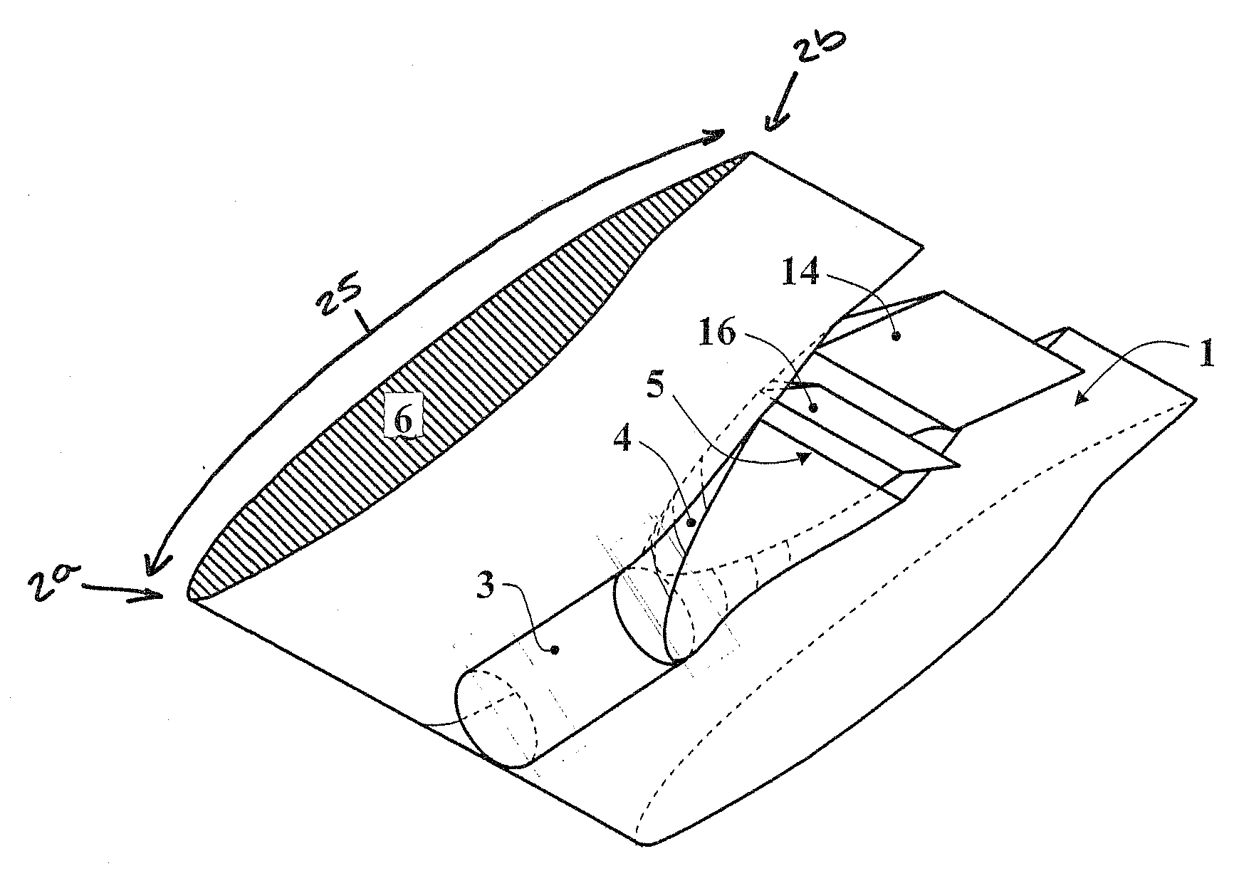
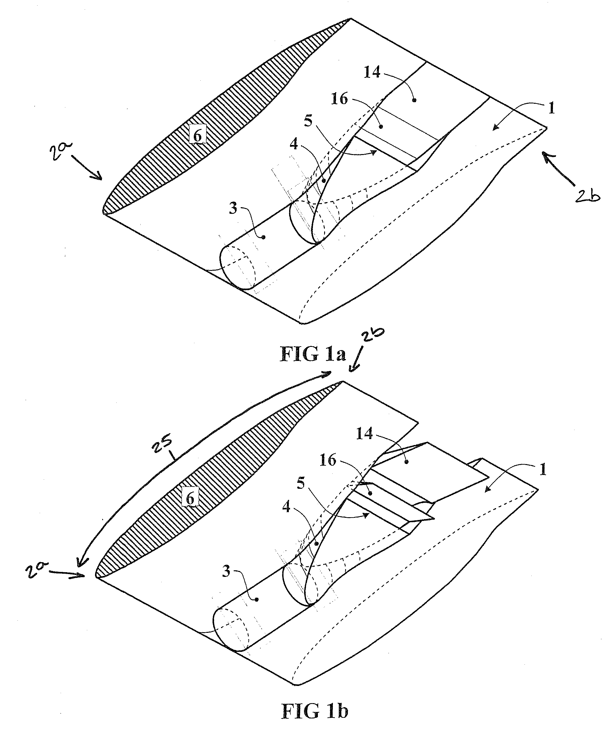
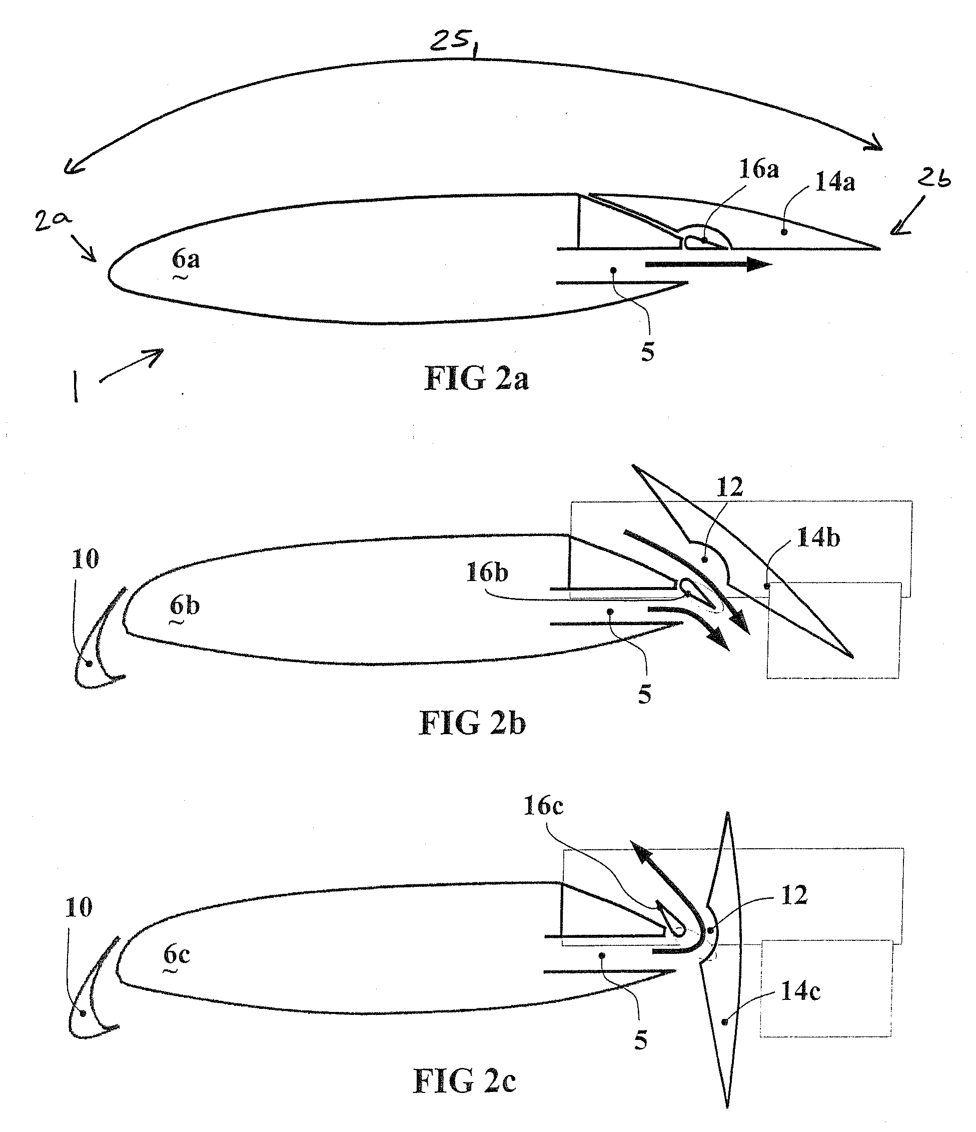
An airfoil for use with an aircraft having an engine positioned such that exhaust from the engine flows under an underside of the airfoil. The airfoil includes an upper surface and a movable control element. The upper surface has a leading edge and a trailing edge. The movable control element is positioned adjacent the trailing edge and is selectively controlled for movement between a first position and a second position. In the first position, the movable control element does not mix fluid flowing over the top of the airfoil with engine exhaust under the airfoil. In the second position, at least some of the fluid flowing over the top of the airfoil mixes under the airfoil with engine exhaust.

Description

CROSS-REFERENCED TO RELATED APPLICATION [0001] The benefit of the filing date of U.S. provisional patent application Ser. No. 60 / 84, filed Jun. 15, 2006, entitled AIRFOIL HAVING A MOVABLE CONTROL SURFACE, is hereby claimed, and the specification thereof is incorporated herein by this reference.TECHNICAL FIELD [0002] The present invention generally relates to aircraft control, and more specifically, improved airfoil flaps for controlling the amount of lift and / or drag produced by an aircraft wing. BACKGROUND OF THE INVENTION [0003] Generally, many types of aircraft utilize flaps to increase or decrease the amount of lift and / or drag of an aircraft wing by changing the amount of camber of the airfoil, or wing shape. The camber refers generally to the asymmetry between the top and the bottom curves of an airfoil. Typically, flaps are hinged surfaces positioned at the trailing edge of a fixed-winged aircraft's wings and which may be extendable or retractable depending on the desired amo...

Claims


Application Information

Patent Timeline
Patent Type & Authority Applications(United States)
IPC IPC(8): B64C15/00
CPCB64C9/20B64D33/04B64D27/18
Inventor NOVAK, CHARLIEBERRY, OWEN T.HARDIN, CHRIS J.MCALLISTER, BOBBY D.
Owner LOCKHEED MARTIN CORP
Learn More