Supercharge Your Innovation With Domain-Expert AI Agents!

Luffing jib tower crane pulling rod and mounting method thereof

The technology of a boom tower crane and an installation method, which is applied to cranes and other directions, can solve problems such as difficult installation and easy confusion of wire ropes, and achieve the effects of reducing installation difficulty, convenient operation, and improving tower safety and tower speed

Pending Publication Date: 2019-05-28
科曼萨建设机械(杭州)有限公司
View PDF0 Cites 2 Cited by
  • Summary
  • Abstract
  • Description
  • Claims
  • Application Information

AI Technical Summary

Problems solved by technology

The disadvantage of this solution is that the wire rope on the hoisting drum is easy to be confused, and two traction ropes are needed to ensure the balance of the moving pulley block during traction, so as to avoid the twisting of the installed luffing rope, and the installation is difficult

Method used


Image

  • Luffing jib tower crane pulling rod and mounting method thereof
  • Luffing jib tower crane pulling rod and mounting method thereof
  • Luffing jib tower crane pulling rod and mounting method thereof

Examples


Embodiment 1

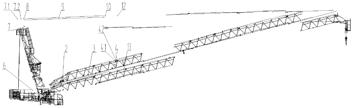
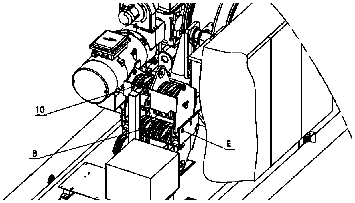
[0044] Referring to the accompanying drawings, a pull rod for a boom tower crane is characterized in that it includes a luffing rope 9, a luffing mechanism 6, an auxiliary mechanism 2, a traction rope 11 for pulling the pulley block 8 to the luffing pull rod set 12, and a moving pulley block 8. The fixed pulley block 10 used for the hinged connection of the tower top 7, the luffing rod group 12 used for the hinged connection of the movable pulley block 8, the tower top 7, the transition pulley 3 installed on the boom 13 to guide the traction rope 11, and the fourth pin shaft E and the traction pulley device 4, the movable pulley block 8 and the fixed pulley block 10 are connected by the luffing rope 11 before leaving the factory, and are fixed by the fourth pin shaft E, and the luffing rope 11 is wound on the luffing mechanism 6; there are two rotating pulley blocks 5 on the movable pulley block 8, which are used to connect the traction rope 11; the auxiliary mechanism 2 is ins...

Embodiment 2

[0051] refer to Figure 1 to Figure 7 , a method for installing a pull rod of a boom tower crane, the installation process of the method includes the following steps:

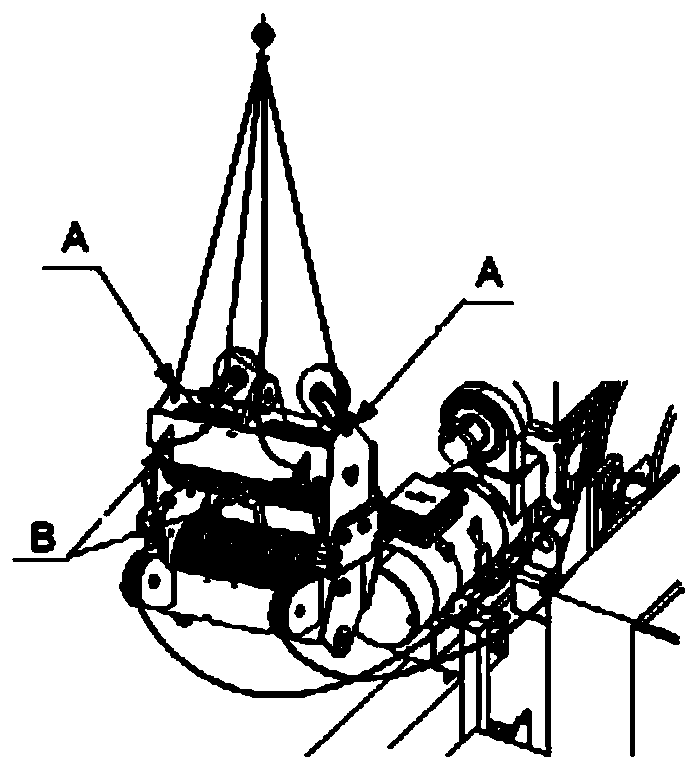
[0052] (S1) Hoist the movable pulley block 8 and the fixed pulley block 10 to the tower top 7 through auxiliary equipment, and simultaneously start the luffing mechanism 6 to loosen the luffing rope 9 .

[0053] (S2) Pass the luffing rope 9 through the rope pulley 7.1, and then install the fixed pulley block 10 on the connecting plate 7.2 of the tower top 7.

[0054] (S3) start auxiliary mechanism 2, draw traction rope 11, traction rope 11 leading ends pass transition pulley 3, pass the 5th pulley 4.1 on the traction pulley device 4 again, pass the rotating pulley block 5 on the movable pulley block 8 again, Get back to traction pulley device 4 at last, be connected and fixed with the 3rd pin shaft 44 on the traction pulley device 4.

[0055] (S4) Remove the pin shaft E connecting the movable pulley block 8 a...


PUM


Abstract

The invention provides a luffing jib tower crane pulling rod. The luffing jib tower crane pulling rod comprises a luffing rope, a luffing mechanism, an auxiliary mechanism, a pulling rope used for pulling a movable pulley block to a luffing pulling rod set, a movable pulley block, a fixed pulley block hinged with a tower tope, a luffing pulling rod set hinged with the movable pulley block, a towertop, transition pulleys for guiding the pulling rope, a fourth pin shaft and a pulling pulley device, wherein the movable pulley block and the fixed pulley block are connected through the luffing rope and are fixed by the fourth pin shaft; the luffing rope is wound on the luffing mechanism; two rotating pulley blocks of the movable pulley block are connected with the pulling rope; the auxiliary mechanism, the pulling pulley device, the transition pulleys and the luffing pulling rod set are mounted on a jib frame; the pulling rope is wound on the auxiliary mechanism; a connecting plate and a rope unwinding pulley are arranged at the tower top; the connecting plate is hinged with the fixed pulley block; the rope unwinding pulley is used as transition of the luffing rope. The invention alsoprovides a mounting method of the luffing jib tower crane pulling rod.

Description

technical field [0001] The invention relates to a pull rod of a boom tower crane and an installation method thereof, belonging to the field of tower cranes. Background technique [0002] There are two ways to install the pull rod in the existing boom tower crane. The first type is that the luffing rope relies on people to thread and wind at high altitude. Due to the long distance between the two pulley blocks (one fixed pulley is at the top of the tower, and the other movable pulley is at the pull rod of the upper chord of the jib, the distance is generally more than 20 meters), and it requires people to work at heights for a long time, so the safety factor is low. The installation process is complicated, especially when the diameter of the luffing rope is relatively large, it is difficult to realize the installation of the luffing rope. The second is to connect the two pulley blocks together (at the top of the tower) when installing the vertical tower. After the luffing r...

Claims


Application Information

Patent Timeline
IPC IPC(8): B66C23/82
Inventor 阿贝多·莫那里斯
Owner 科曼萨建设机械(杭州)有限公司
Features
  • R&D
  • Intellectual Property
  • Life Sciences
  • Materials
  • Tech Scout
  • Unparalleled Data Quality
  • Higher Quality Content
  • 60% Fewer Hallucinations
Learn More