
Wiring device for magnetic suspension bearing, compressor and refrigeration equipment

A magnetic suspension bearing and wiring device technology, applied in mechanical equipment, bearings, shafts and bearings, etc., can solve the problems of difficult fixing, easy breakage and complexity of lead wires, so as to improve reliability, prolong the service life of lead wires, and simplify wiring and lead wires. The effect of the operation steps

Pending Publication Date: 2019-05-28
GREE ELECTRIC APPLIANCES INC
View PDF0 Cites 1 Cited by
  • Summary
  • Abstract
  • Description
  • Claims
  • Application Information

AI Technical Summary

Problems solved by technology

[0003] The first object of the present invention is to provide a wiring device for magnetic suspension bearings, to solve the problem that the lead wires of the existing magnetic suspension bearings are complicated to operate, and the exposed leads are difficult to fix and easy to break.

Method used


Image

  • Wiring device for magnetic suspension bearing, compressor and refrigeration equipment
  • Wiring device for magnetic suspension bearing, compressor and refrigeration equipment
  • Wiring device for magnetic suspension bearing, compressor and refrigeration equipment

Examples


Embodiment 1

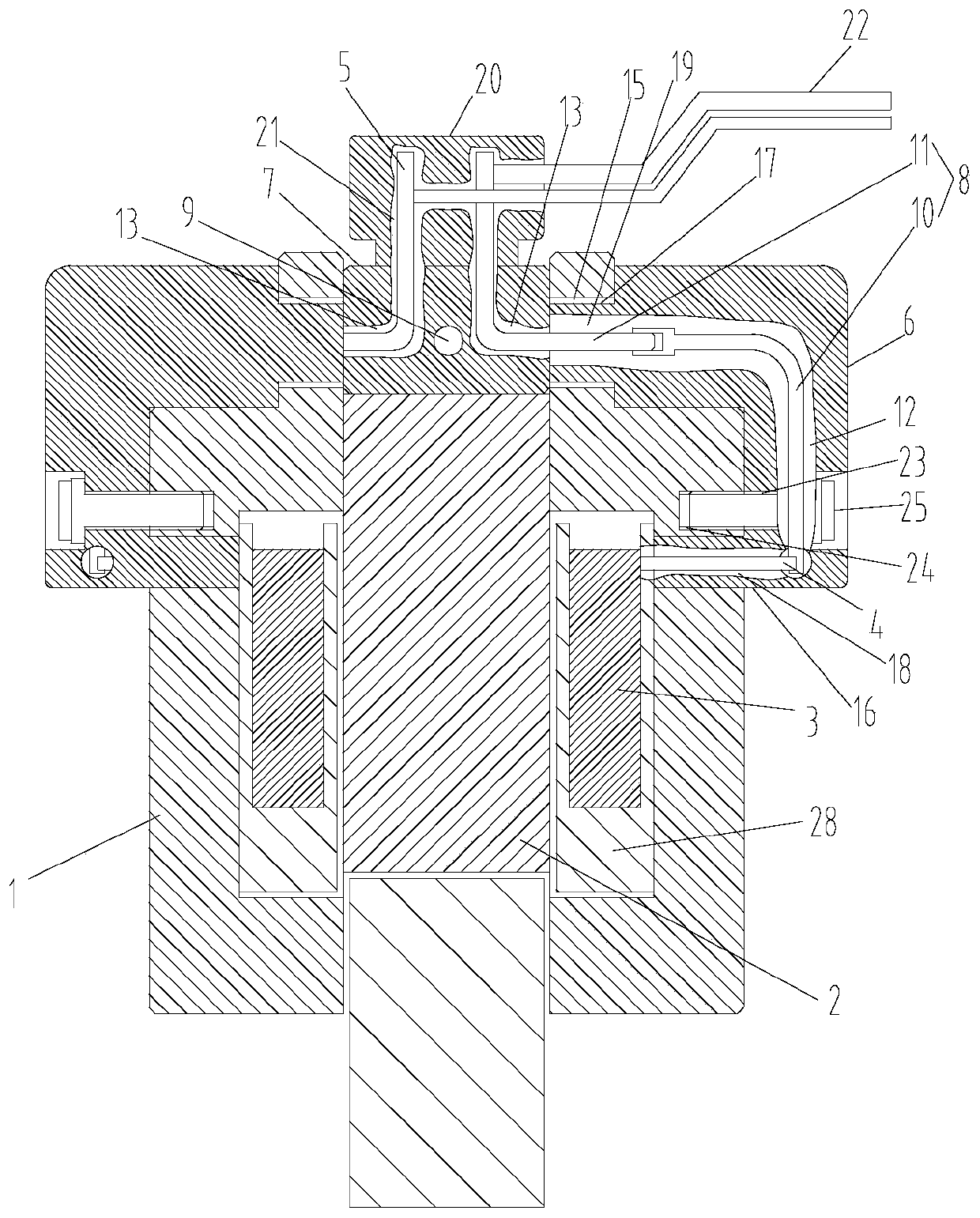
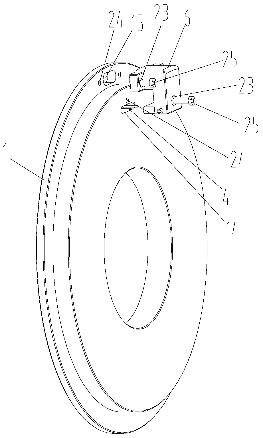
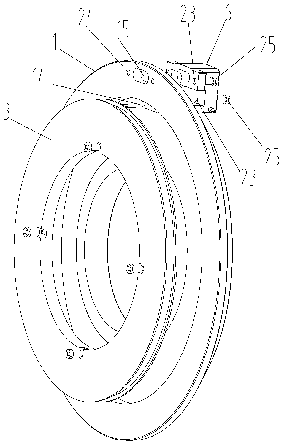
[0033] combined with Figure 1-9 As shown, this embodiment provides a wiring device for magnetic suspension bearings. In order to more clearly show the matching relationship between the wiring device and the magnetic suspension bearing, the attached figure 1 Also shows part of the magnetic suspension bearing, and by attaching figure 2 and 3 Further explain the relationship between the two.

[0034] combined with Figure 1-3 As shown, the magnetic suspension bearing of this embodiment includes an outer iron core 1, an inner iron core 2 and a control winding 3, the number of outer iron cores 1 is two, and the two outer iron cores 1 are symmetrically arranged on both sides of the inner iron core 2 , since the magnetic suspension bearing can be regarded as a symmetrical structure, so the figure 2 and image 3 Only one side of the outer core 1 is shown.

[0035] recombine figure 1 As shown, the control winding 3 of this embodiment is arranged between the two outer iron cor...

Embodiment 2

[0049] This embodiment provides a compressor, which has the wiring device and the magnetic suspension bearing as described in the first embodiment. Since the improvement of the compressor of this embodiment is only the wiring device and the magnetic suspension bearing, the rest of the structure of the compressor It is the same as the prior art, so this embodiment does not describe the compressor, nor describe other components of the compressor, but those skilled in the art can fully understand the above structure.

Embodiment 3

[0051] This embodiment provides a refrigeration device, which may be an air conditioner, which has the compressor described in Embodiment 2. Similarly, the improvement of the refrigeration device in this embodiment is only the wiring device of the compressor and magnetic suspension bearings, while the rest of the structure of the refrigeration equipment is the same as the prior art, so this embodiment does not illustrate the refrigeration equipment with drawings.


PUM


Abstract

The invention discloses a wiring device for a magnetic suspension bearing, a compressor and refrigeration equipment. The magnetic suspension bearing comprises a control winding with a first wiring endand a second wiring end, a first conductive structure and a second conductive structure are arranged in the wiring device, the first conductive structure is conductively connected with the first wiring end, and the second conductive structure is conductively connected with the second wiring end, wherein the first conductive structure is provided with an external connection end connected with an outer power source. According to the provided wiring device for the magnetic suspension bearing, the wiring and wire guiding operation steps are simplified, the conductive structures are arranged in the wiring device, the problem about lead exposure cannot happen, accordingly, the service life of leads is prolonged, and the running reliability of the magnetic suspension bearing is improved.

Description

technical field [0001] The invention relates to the technical field of magnetic suspension bearings, in particular to a wiring device for magnetic suspension bearings, a compressor and refrigeration equipment. Background technique [0002] The wiring device of the existing hybrid axial magnetic suspension bearing mainly includes two axial control windings, four winding lead wires, permanent magnets, iron cores and thrust plates and other components. Each axial control winding is connected to two winding lead wires. Wire. Due to the special structural form of the hybrid axial thrust bearing, its permanent magnet needs to have an independent and complete magnetic circuit in the iron core, so the entire structure is a closed form from the cross-section, and the two control windings need Series connection, one connection method is to connect a common terminal inside the bearing, and then lead out the remaining two power lines of the control winding, and the other connection met...

Claims


Application Information

Patent Timeline
Patent Type & Authority Applications(China)
IPC IPC(8): F16C32/04
Inventor 苏久展张芳龚高张超李欣董如昊邓明星刘鹏辉王飞吴瑞赵伟杰魏志韬王建辉钟敦颖刘湛钦
Owner GREE ELECTRIC APPLIANCES INC
Learn More