Debugging and fixing device of turbine blade vibration on-line monitoring equipment
A technology of steam turbine blades and vibrating equipment, applied in the field of steam turbines, can solve the problem that the sensor is not easy to adjust and fix, and achieve the effect of reducing the number of adjustments and speeding up the debugging work
- Summary
- Abstract
- Description
- Claims
- Application Information
AI Technical Summary
Problems solved by technology
Method used
Image
Examples
specific Embodiment approach 1
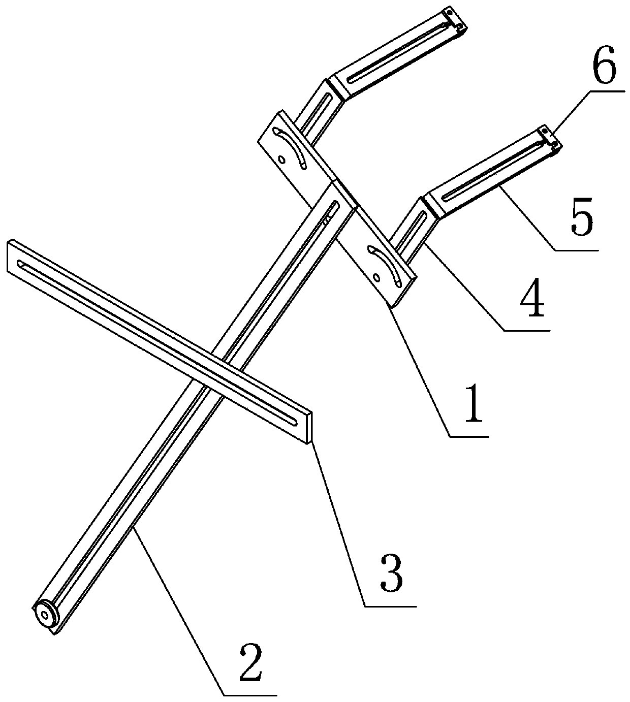
[0016] Specific implementation mode one: combine figure 1 To illustrate this embodiment, this embodiment includes a circumferential fixed plate 1, a vertical adjustment plate 2, a horizontal tension plate 3, two circumferential swing plates 4 and two axial adjustment plates 5;
[0017] The horizontal tie plate 3 is fixed on the frame of the on-line monitoring steam turbine blade vibration equipment, the vertical adjustment plate 2 is fixed on the horizontal tie plate 3 by bolts and can be adjusted horizontally, and each circumferential fixed plate 1 is fixed on the vertical plate by bolts. straight on the adjustment plate 2 and can be adjusted up and down, each circumferential swing plate 4 is fixed on each circumferential fixed plate 1 by bolts and can swing at a certain angle, and each axial adjustment plate 5 is fixed on each axial swing plate 4.
specific Embodiment approach 2
[0018] Specific implementation mode two: combination figure 1 To illustrate this embodiment, in this embodiment, each circumferential fixed plate 1 is processed with two arc-shaped long grooves and two fixed holes, and each circumferential swing plate 4 is processed with a first long groove, and each circumferential The arc-shaped slots and fixing holes on the fixed plate 1 are respectively connected with the first slots of each circumferential swing plate 4 by bolts.
[0019] Other compositions and connections are the same as in the first embodiment.
specific Embodiment approach 3
[0020] Specific implementation mode three: combination figure 1 To illustrate this embodiment, in this embodiment, each axial adjustment plate 5 is processed with a second long groove, the end of each axial adjustment plate 5 is processed with a gap, and the second long groove on each axial adjustment plate 5 is The groove and the gap are connected, and a baffle plate 6 is provided at the position of the gap.
[0021] Other compositions and connections are the same as in the first embodiment.
PUM
 Abstract
Description
Claims
Application Information
 - R&D
- Intellectual Property
- Life Sciences
- Materials
- Tech Scout
- Unparalleled Data Quality
- Higher Quality Content
- 60% Fewer Hallucinations
Browse by: Latest US Patents, China's latest patents, Technical Efficacy Thesaurus, Application Domain, Technology Topic, Popular Technical Reports.
© 2025 PatSnap. All rights reserved.Legal|Privacy policy|Modern Slavery Act Transparency Statement|Sitemap|About US| Contact US: help@patsnap.com

