
Measurement task setting method for shaft detection instrument

A technology for measuring tasks and setting methods, applied in measuring devices, instruments, and optical devices, etc., can solve the problems of high work intensity, low efficiency, and difficulty in online measurement, so as to improve the accuracy and stability of measurement, and improve the measurement accuracy. Fully parameterized effects

Active Publication Date: 2019-05-28
武汉联扬科技有限公司
View PDF5 Cites 2 Cited by
  • Summary
  • Abstract
  • Description
  • Claims
  • Application Information

AI Technical Summary

Problems solved by technology

At present, the measurement methods for shaft parts are divided into contact measurement and non-contact measurement. The contact measurement method has high work intensity and low efficiency, and it is difficult to realize online measurement, which cannot meet the multi-dimensional parameters of existing shaft parts. Fast and accurate measurement; although non-contact measurement overcomes the above-mentioned defects of contact measurement, most non-contact measurement has fewer measurement tasks and cannot fully meet the needs of parameter measurement of shaft parts. At the same time, the measurement accuracy and Efficiency does not meet expectations

Method used


Image

  • Measurement task setting method for shaft detection instrument
  • Measurement task setting method for shaft detection instrument
  • Measurement task setting method for shaft detection instrument

Examples


Embodiment 1

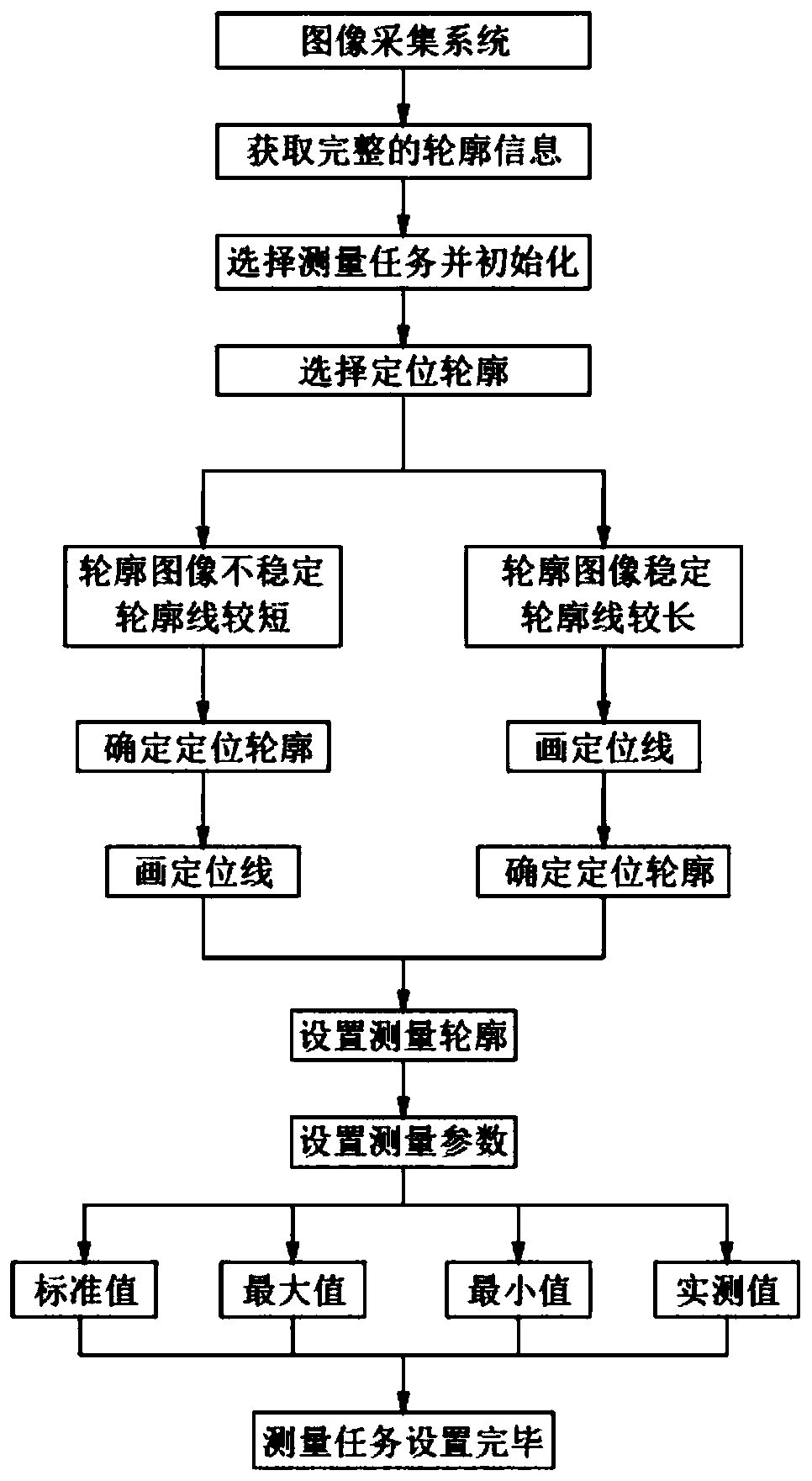
[0060] Embodiment 1, taking setting the diameter of the measurement shaft as an example, explains the specific task setting process. In this embodiment of the shaft diameter measurement task setting embodiment, the contour image information of the part to be measured is stable and the contour line is long, such as Figure 4 ~ Figure 6 As shown, the specific setting process of the measurement task is as follows:

[0061] (1) Obtain the complete contour image of the workpiece to be measured;

[0062] (2) Select the relatively stable contour of the contour image information of the part to be measured as the positioning contour, because in this embodiment, the upper contour edge information of the shaft part to be measured is stable, so the upper contour is selected as the positioning contour, so a short straight line is drawn Intersect with the upper contour of the shaft part to be measured (eg Figure 4 shown), this short straight line is the positioning line, and the upper con...

Embodiment 2

[0065] Embodiment 2, take setting the distance between the measuring line and the line as an example, that is, Figure 7 with Figure 8 As shown, the distance between the left and right vertical lines is measured, and the specific task setting process is described: in this measurement task setting example, because the left and right vertical lines are too short to be easily positioned, it is necessary to select The contour image information near the part to be measured is stable and the longer contour is used as the positioning contour. The specific setting process of the measurement task is as follows:

[0066] (1) Obtain the complete contour image of the workpiece to be measured;

[0067] (2) Select the longer contour line near the contour line of the part to be measured as the positioning contour, and then draw a short straight line to intersect with the longer contour line (such as Figure 7 shown), this short straight line is the positioning line, and the longer contour...


PUM


Abstract

The invention discloses a measurement task setting method for a shaft detection instrument. The method comprises the following steps that integral outline image information is acquired through an image collection system; a measurement task is selected, and initialization is conducted; a locating outline is selected; a measurement outline is set; measurement parameters are set; after being set, themeasurement task is stored. According to the method, firstly, a shaft part is located, the accuracy of outline selection is improved, stability and accuracy of subsequent measurement are improved, parameters used for measurement are complete, and different requirements of users are met.

Description

technical field [0001] The invention relates to the technical field of image measurement, in particular to a measurement task setting method for an axis inspection instrument. Background technique [0002] A large number of shaft parts are used in machinery, automobile, electromechanical and other industries, including automobile drive shafts, gear shafts, main shafts of machine tools and roller shafts of textile machinery, etc. The machining accuracy of shaft parts directly affects the processing quality of products. It even directly affects the scrap rate of the product. Accurate measurement of the dimensions of the shaft parts is one of the important means to ensure the machining accuracy. The precision and accuracy of the measurement largely determine the product quality of the shaft parts. At present, the measurement methods for shaft parts are divided into contact measurement and non-contact measurement. The contact measurement method has high work intensity and low ef...

Claims


Application Information

Patent Timeline
Patent Type & Authority Applications(China)
IPC IPC(8): G01B11/24G01B11/26G01B11/02G01B11/08
Inventor 沈满德方锑张法全周利兵闵玉瑾
Owner 武汉联扬科技有限公司
Learn More