Corn crankshaft threshing machine

A threshing machine and crankshaft technology, applied in threshing equipment, agricultural machinery and implements, applications, etc., can solve problems such as machine jamming and incomplete corn threshing, and achieve the effect of easy promotion and application and strong structural continuity

Inactive Publication Date: 2019-05-31
广西万联重工科技有限公司
View PDF0 Cites 0 Cited by
  • Summary
  • Abstract
  • Description
  • Claims
  • Application Information

AI Technical Summary

Problems solved by technology

[0003] The existing corn thresher uses corn directly into the feed port, and the corn is threshed in the threshing bin, which will lead to incomplete corn threshing, or the state of the machine jam

Method used


Image

  • Corn crankshaft threshing machine
  • Corn crankshaft threshing machine

Examples


Embodiment 1

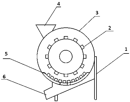
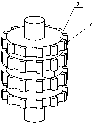
[0018] Such as Figure 1-2 As shown, a corn crankshaft threshing machine includes a frame 1, an off-line bin 3 is arranged on the frame 1, and a threshing roller is arranged in the threshing bin 3; a material inlet 4 and a discharge port at the bottom are arranged outside the threshing bin 3 7; the described threshing roller is a crankshaft threshing roller 2, and the outside of the crank of the crankshaft threshing roller 2 is provided with a threshing tooth 7; below the crankshaft threshing roller 2, a threshing arc 5 corresponding to the crankcase is provided; the described The number of the cranks of the threshing crank roller 2 matches the feed opening 4 and the discharge opening. There are at least five threshing teeth on each crank.

[0019] When in use: Put the corn into the material inlet 4 of the corresponding crank, and the corn will be threshed quickly through the threshing teeth 7 on the threshing roller 2 of the crankshaft and the threshing arc 5 at the bottom, ...

Embodiment 2

[0021] Such as Figure 1-2 As shown, a corn crankshaft threshing machine includes a frame 1, an off-line bin 3 is arranged on the frame 1, and a threshing roller is arranged in the threshing bin 3; a material inlet 4 and a discharge port at the bottom are arranged outside the threshing bin 3 7; the described threshing roller is a crankshaft threshing roller 2, and the outside of the crank of the crankshaft threshing roller 2 is provided with a threshing tooth 7; below the crankshaft threshing roller 2, a threshing arc 5 corresponding to the crankcase is provided; the described The number of the cranks of the threshing crank roller 2 matches the feed opening 4 and the discharge opening. Each crank is provided with six threshing teeth.

[0022] The working principle is consistent with that of Example 1.

Embodiment 3

[0024] Such as Figure 1-2 As shown, a corn crankshaft threshing machine includes a frame 1, an off-line bin 3 is arranged on the frame 1, and a threshing roller is arranged in the threshing bin 3; a material inlet 4 and a discharge port at the bottom are arranged outside the threshing bin 3 7; the described threshing roller is a crankshaft threshing roller 2, and the outside of the crank of the crankshaft threshing roller 2 is provided with a threshing tooth 7; below the crankshaft threshing roller 2, a threshing arc 5 corresponding to the crankcase is provided; the described The number of the cranks of the threshing crank roller 2 matches the feed opening 4 and the discharge opening. There are at least five threshing teeth on each crank.

[0025] The crankshaft threshing roller can be placed vertically to achieve the threshing effect.


PUM


Abstract

The invention provides a corn crankshaft threshing machine. The corn crankshaft threshing machine comprises a machine frame, a threshing bin is arranged on the machine frame, and a threshing roller isarranged in the threshing bin; a feeding opening and a bottom discharging opening are formed outside the threshing bin; the threshing roller is a crankshaft threshing roller, and threshing teeth arearranged on the outer side of a crankshaft of the crankshaft threshing roller; a threshing arc corresponding to a crankcase is arranged below the crankshaft threshing roller; the number of the feedingopening and the number of the discharging opening are matched with the number of the crankshaft of the crankshaft threshing roller. The corn crankshaft threshing machine is simple in structure, and can achieve rapid threshing.

Description

technical field [0001] The invention relates to the technical field of agricultural machinery, in particular to a corn crank thresher. Background technique [0002] Annual tall herb. Culms erect, usually unbranched, 1-4 m tall, with aerial strut roots at each node at base. Leaf sheaths with transverse veins; ligule membranous, about 2 mm long; leaf blade flat and wide, linear-lanceolate, base rounded and ear-shaped, glabrous or pilose, midrib stout, margin slightly scabrous. The terminal male panicle is large, the main axis, the raceme axis and the axils are finely pubescent; the male spikelets are twin, up to 1 cm long, and the spikelet peduncle is 1-2 mm long and 2-2 mm long, respectively 4 mm, finely pilose; two glumes nearly equal in length, membranous, with about 10 veins, ciliated; lemma and palea hyaline membranous, slightly shorter than glumes; anthers orange-yellow; about 5 mm long. The female inflorescence is enclosed by most broad sheath-like bracts; the female...

Claims


Application Information

Patent Timeline
Patent Type & Authority Applications(China)
IPC IPC(8): A01F11/06A01F12/10A01F12/18
Inventor 唐平生庞武
Owner 广西万联重工科技有限公司
Why Eureka
Try Eureka