
Anesthetic head frame

A head frame and connecting frame technology, applied in the field of anesthesia head frame, can solve the problems of elevated airway pressure, operation interference, inconvenient breathing management, etc.

Pending Publication Date: 2019-05-31
WENZHOU PEOPLES HOSPITAL
View PDF0 Cites 3 Cited by
  • Summary
  • Abstract
  • Description
  • Claims
  • Application Information

AI Technical Summary

Problems solved by technology

The existing anesthesia head frame is generally L-shaped, generally rotatable and set on one side of the anesthesia bed, and the installation position is fixed to support the sterile towel. Since the anesthesia head frame is in a one-sided position, it can be rotated to a suitable blocking position after the support is erected. If the surgeon lays the drape before the completion of the endotracheal intubation or emergency endotracheal intubation is required during the operation, the anesthesia head frame will still occupy the operating space of the anesthesiologist after the angled rotation, so that the anesthesiologist needs to perform endotracheal intubation on the patient. The operations completed on the head and face are disturbed, which affects the efficiency of anesthesia; in general anesthesia to control breathing or mask oxygen supply, it is necessary to use a breathing threaded tube. It is not convenient for breathing management because of the patient's mouth and nose; and the existing anesthesia head frame has a single function, and the anesthesia bed also has a single function, which cannot meet the requirements of the existing anesthesia operation

Method used


Image

  • Anesthetic head frame
  • Anesthetic head frame
  • Anesthetic head frame

Examples


Embodiment Construction

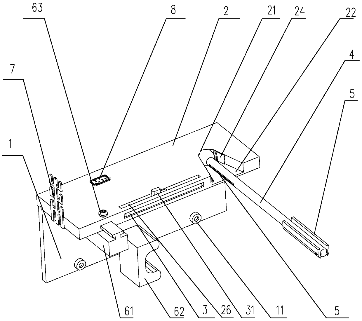
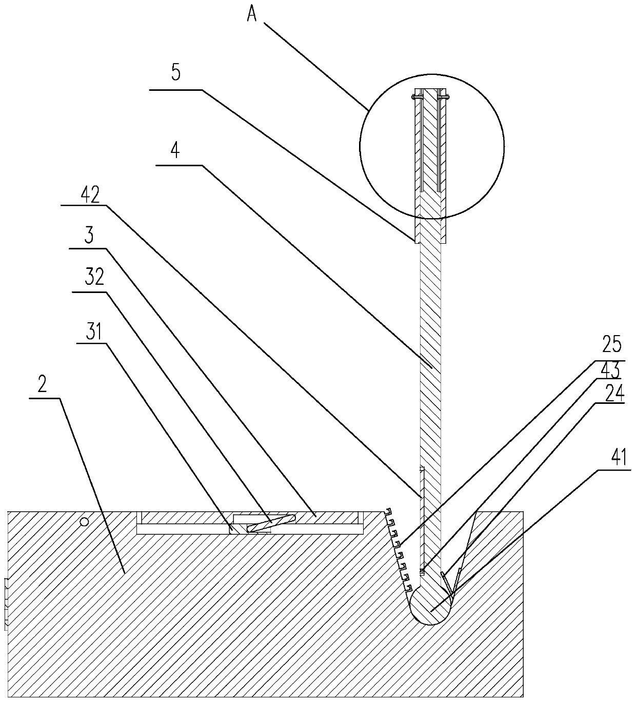
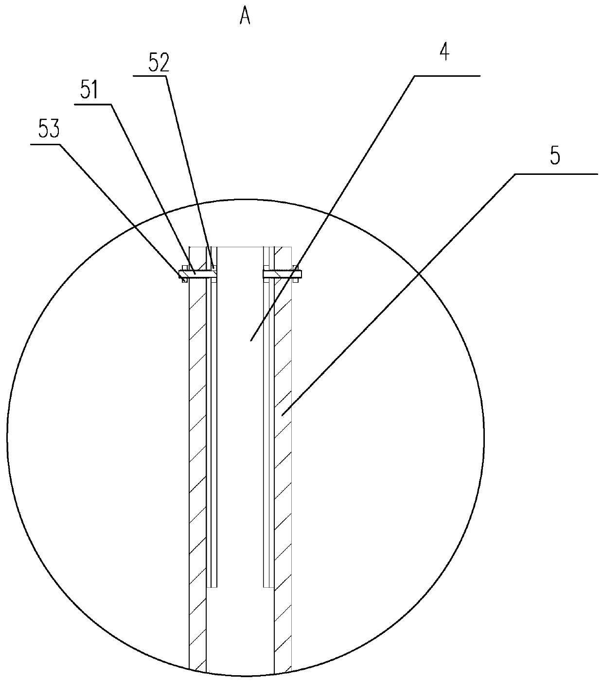
[0027] Depend on Figure 1 to Figure 4It can be seen that an anesthesia head frame is disclosed, including a positioning frame and a connecting frame for slidingly arranged on the bed body along the width direction of the bed body. The connecting frame includes a sliding base 1 and a storage board 2. The sliding base 1 The bottom is provided with a pulley 11, and the storage board 2 is slidably arranged on the sliding base 1 along the width direction of the bed body, and an accommodating groove is formed on the side wall of the storage board 2. The airing rod 3 of the sterile towel, the storage board 2 is provided with a mounting groove 21, the positioning frame includes a connecting rod 4 and a positioning rod 5 for abutting against the popliteal fossa of the patient, and the positioning rod 5 is connected to the The rod 4 is movably connected, and the connecting rod 4 is rotatably arranged in the mounting groove 21, and the mounting groove 21 extends to the outside of the st...


PUM


Abstract

The invention discloses an anesthetic head frame. The anesthetic head frame comprises a positioning frame and a connecting frame which is slidably arranged on a bed body in the width direction of thebed body, the connecting frame comprises a sliding base and a storage plate, wheels are arranged at the bottom of the sliding base, the storage plate is slidably arranged on the sliding base in the width direction of the bed body, and a containing groove is formed in the side wall of the storage plate; a hanging rod used for hanging a sterile towel is rotationally arranged in the containing groove, and a mounting groove is formed in the storage plate; the positioning frame comprises a connecting rod and a positioning rod used for abutting against the popliteal space of a patient, the positioning rod is movably connected with the connecting rod, and the connecting rod is rotationally arranged in the mounting groove; the mounting groove extends out of the storage plate to form a swing grooveso that the connecting rod can swing in the horizontal direction of the storage plate, and a back cushion used for pushing the cervical vertebra of the patient is further arranged on the bottom faceof the storage plate. The anesthetic head frame has more comprehensive functions, and also has an assisting effect on anesthesia operations.

Description

technical field [0001] The invention relates to the technical field of medical instruments, in particular to an anesthesia head frame. Background technique [0002] The anesthesia head frame is one of the accessories of the operating bed. It is a medical equipment accessory used to support the sterile towel during the operation, cover the patient and expose the face, and strictly distinguish the sterile area and the sterile area, so that the anesthesiologist can observe the patient's breathing. The existing anesthesia head frame is generally L-shaped, generally rotatable and set on one side of the anesthesia bed, and the installation position is fixed to support the sterile towel. Since the anesthesia head frame is in a one-sided position, it can be rotated to a suitable blocking position after the support is erected. If the surgeon lays the drape before the completion of the endotracheal intubation or emergency endotracheal intubation is required during the operation, the a...

Claims


Application Information

Patent Timeline
Patent Type & Authority Applications(China)
IPC IPC(8): A61G13/12
Inventor 缪项慧
Owner WENZHOU PEOPLES HOSPITAL
Learn More