Gynecological production nursing cleaning device

A cleaning device, obstetrics and gynecology technology, applied in cleaning methods and utensils, cleaning methods using tools, cleaning methods using liquids, etc., can solve problems such as easy loosening, narrow space, and reduced maintenance efficiency, so as to achieve easy installation and The effect of disassembly, meeting the needs of use, and improving maintenance efficiency

Inactive Publication Date: 2019-05-31
孙晶
View PDF1 Cites 2 Cited by
  • Summary
  • Abstract
  • Description
  • Claims
  • Application Information

AI Technical Summary

Problems solved by technology

[0003] The publication number is CN109288242A, which discloses a cleaning device for obstetrics and gynecology, including a box body, a timing button, a cleaning cylinder, a liquid storage tank, a waste liquid pipe mounting seat, a drive motor and a liquid supply pump. The box body is rectangular The box structure, but this invention does not involve how to replace the brush strips. The general brush strips are usually fixed with bolts, but the way of fixing them with bolts is cumbersome and needs to be installed inside the cleaning cylinder. It is easy to replace the brush strips frequently. The external thread on the screw is worn, and the bolt is in contact with the liquid in the cleaning cylinder for a long time, which is easy to rust. Once worn or rusted, it is easy to loosen. Once loosened, the cleaning efficiency will be affected. The circuit board used for timing adjustment of this invention is located in Inside the device, once a failure occurs, maintenance personnel need to repair it inside. The internal space of the device is small, which is not convenient for maintenance personnel to operate, which reduces the maintenance efficiency, and there is room for improvement

Method used


Image

  • Gynecological production nursing cleaning device
  • Gynecological production nursing cleaning device
  • Gynecological production nursing cleaning device

Examples


Embodiment Construction

[0024]The following will clearly and completely describe the technical solutions in the embodiments of the present invention with reference to the accompanying drawings in the embodiments of the present invention. Obviously, the described embodiments are only some, not all, embodiments of the present invention.

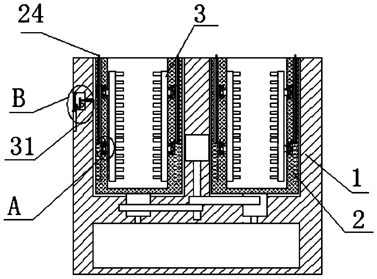
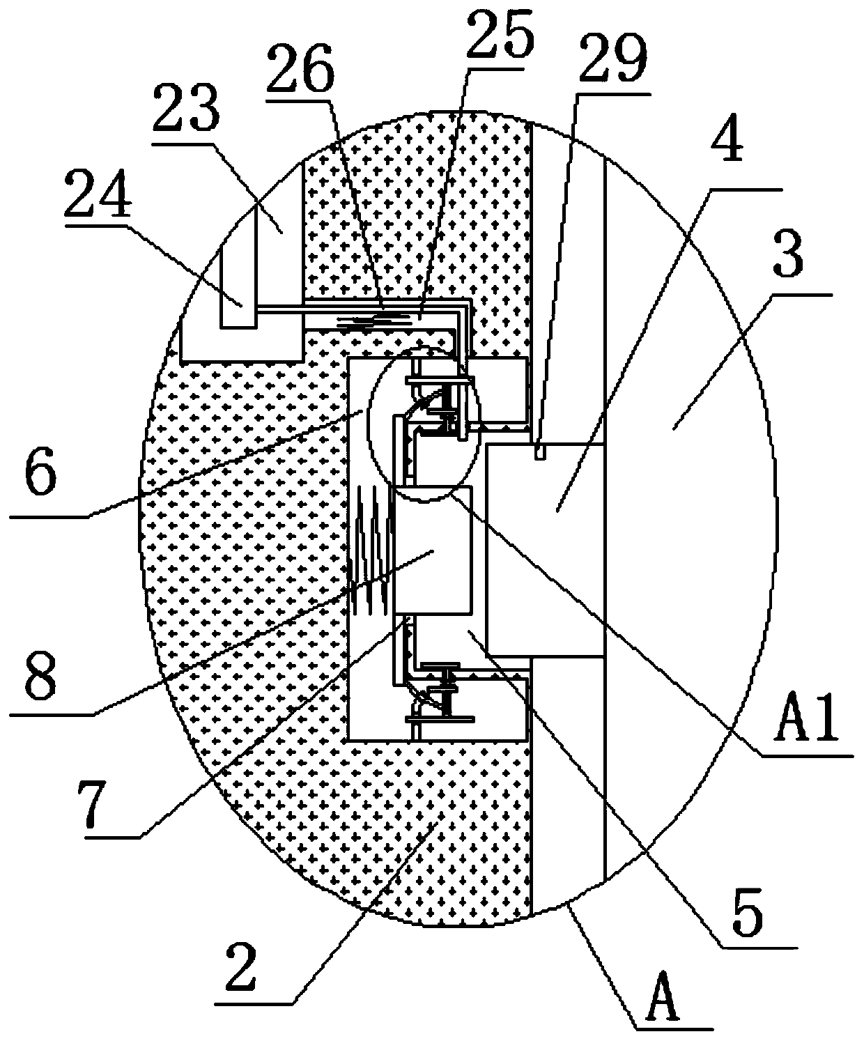
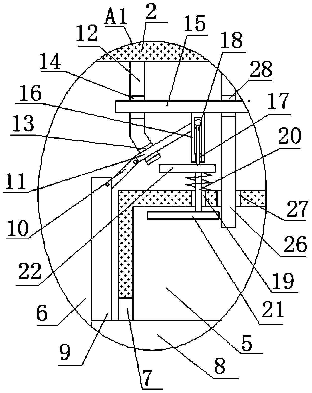
[0025] refer to Figure 1-5 , a kind of obstetrics and gynecology production care cleaning device, comprising a box body 1, a plurality of cleaning tubes 2 are arranged in the box body 1, a plurality of brush strips 3 are movably installed in the cleaning tube 2, and one of the brush strips 3 is close to the cleaning tube 2 Two mounting columns 4 are fixedly installed on the side, and one side of the mounting column 4 is provided with two mounting grooves 5 on the inner wall of one side of the box body 1, and the end of the mounting column 4 away from the brush bar 3 extends into the mounting groove 5, One side of the installation groove 5 is provided with a U-shaped ...


PUM


Abstract

The invention discloses a gynecological production nursing cleaning device. The gynecological production nursing cleaning device comprises a box body. A plurality of cleaning cylinders are arranged inthe box body. A plurality of brush strips are movably mounted in the cleaning cylinders. Two mounting columns are fixedly arranged on one sides, close to the cleaning cylinders, of the brush strips.Two mounting grooves which are formed in an inner wall of one side of the box body are formed in one sides of the mounting columns. The gynecological production nursing cleaning device is easy to operate. The mounting columns of the brush strips can be aligned with the mounting grooves to move, so that mounting can be completed. A pull rod can be pulled, and the brush strips can be moved, so thatmounting and dismounting of the brush strips are facilitated. The mounting columns are pressed by push plates, so that the brush strips can be prevented from shaking after being mounted. An L-type rodis moved into a second clamping groove, so that the brush strips can be fixed. When a circuit board used for time adjusting has faults, a T-type clamping rod is pulled, and the pull rod is pushed downwards, so that the circuit board can be popped out of a circuit board groove, maintenance personnel can repair the circuit board with enough space, the maintenance efficiency is improved, and use requirements of people are met.

Description

technical field [0001] The invention relates to the technical field of cleaning equipment, in particular to a cleaning device for obstetrics and gynecology. Background technique [0002] As the name suggests, cleaning equipment is mechanical equipment designed for cleaning. Cleaning equipment plays a role in efficient cleaning. It reduces the labor cost of cleaning and improves work efficiency and cleanliness. It is indispensable in modern society. In the field of medical and health It is often necessary to clean and disinfect medical equipment with cleaning equipment. [0003] The publication number is CN109288242A, which discloses a cleaning device for obstetrics and gynecology, including a box body, a timing button, a cleaning cylinder, a liquid storage tank, a waste liquid pipe mounting seat, a drive motor and a liquid supply pump. The box body is rectangular The box structure, but this invention does not involve how to replace the brush strips. The general brush strips...

Claims


Application Information

Patent Timeline
IPC IPC(8): B08B3/04B08B1/00
Inventor 孙晶
Owner 孙晶
Why Eureka
Try Eureka