
Relining manipulator crane span structure

A bridge structure and manipulator technology, applied in the direction of manipulators, metal processing, metal processing equipment, etc., can solve the problems of insufficient bridge structure, time-saving and labor-saving, poor safety, and large frictional damage to components, so as to achieve time-saving and labor-saving work of replacing lining trolleys. Effect of improving service life and reducing friction loss

Inactive Publication Date: 2019-05-31
合肥市春华起重机械有限公司
View PDF11 Cites 4 Cited by
  • Summary
  • Abstract
  • Description
  • Claims
  • Application Information

AI Technical Summary

Problems solved by technology

[0004] The purpose of the present invention is to solve the problem that the liner is not stable enough when the liner is transported by the liner trolley in the existing liner bridge structure, the liner is easy to shake or fall off, and the liner and the bridge structure The frictional damage of the components is large, and the safety of the staff working on the bridge structure is poor, and the flexibility of the bridge structure to be adjusted is poor, the adjustable range is low, and the position of the bridge structure to transport the liner to the mill is not accurate and suitable , and the use of the bridge structure is not enough to save time and effort, and the problem of inconvenient operation, and a bridge structure with relining manipulator is proposed

Method used


Image

  • Relining manipulator crane span structure
  • Relining manipulator crane span structure
  • Relining manipulator crane span structure

Examples


Embodiment Construction

[0049] The technical solutions of the present invention will be clearly and completely described below in conjunction with the embodiments. Apparently, the described embodiments are only some of the embodiments of the present invention, not all of them. Based on the embodiments of the present invention, all other embodiments obtained by persons of ordinary skill in the art without creative efforts fall within the protection scope of the present invention.

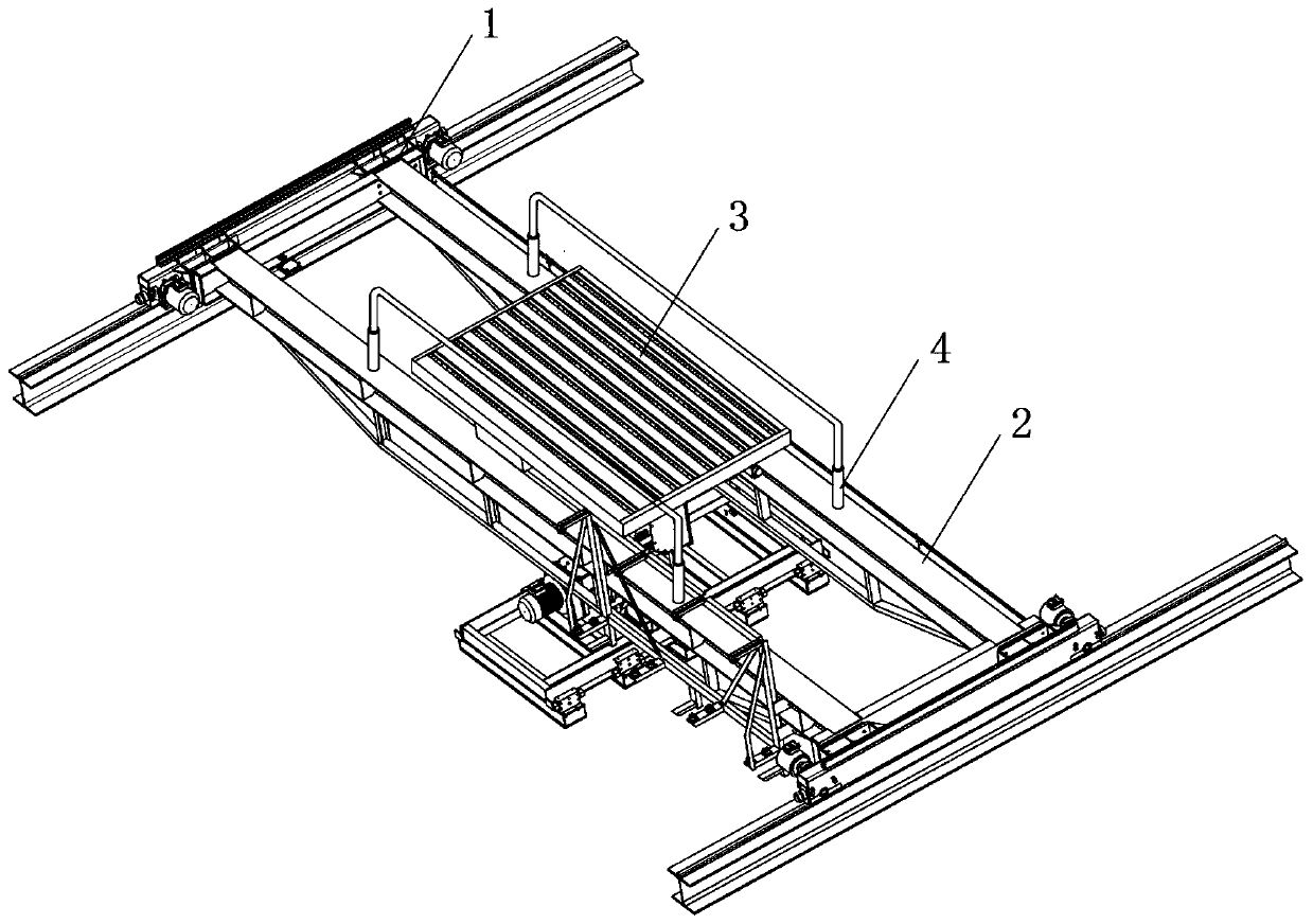
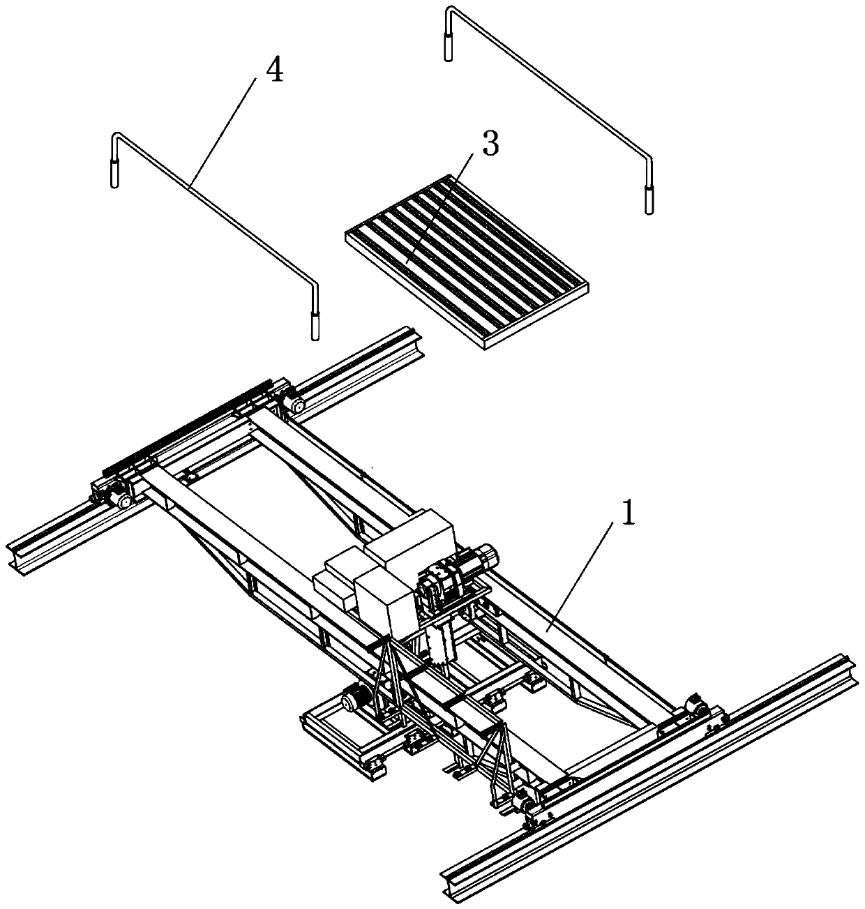
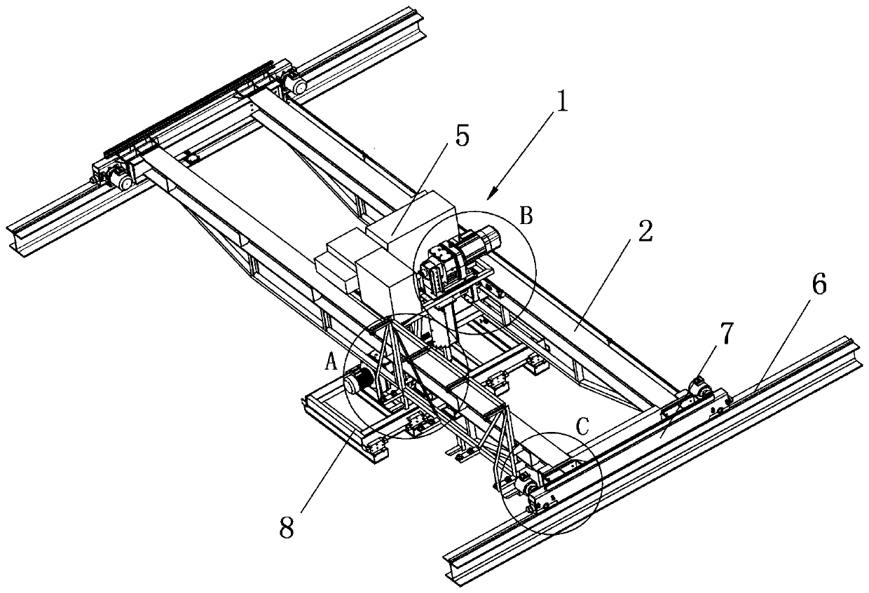
[0050] see Figure 1-14 As shown, a relining manipulator bridge structure includes a platform 1, a cantilever beam 2, a relining trolley 3, a guardrail 4 and a side frame 6. Two cantilever beams 2 are arranged in parallel in the middle of the platform 1, and two cantilever beams 2 A relining trolley 3 is sleeved between them, guardrails 4 are arranged longitudinally above the middle of the two cantilever beams 2, and both ends of the two cantilever beams 2 are vertically provided with sleeve clamping seats 7, and both sleev...


PUM


Abstract

The invention discloses a relining manipulator crane span structure. The relining manipulator crane span structure comprises a stand, cantilever beams, a relining trolley, guard bars and side joint frames; the two cantilever beams are arranged in the middle of the stand in parallel; the relining trolley is arranged between the two cantilever beams in a sleeving mode; the guard bars are longitudinally arranged on the upper portions of the middles of the two cantilever beams; the two ends of the two cantilever beams are vertically provided with sleeve clamping bases; and the side joint frames are arranged below the two sleeve clamping bases. The relining manipulator crane span structure has the beneficial effects that a worker puts a lining plate on a lining conveying trolley by standing onthe cantilever beams to convey the lining plate, and when the worker stands on the cantilever beams, the worker leans on or holds extending bars of the guard bars, so that operation safety of the worker on the crane span structure is ensured; and hydraulic pumps below the two ends of the guard bars drive the extending bars to ascend or descend through hydraulic rods, so that the use height of theoverall guard bars is adjusted, it is ensured that workers of different heights can use the guard bars more comfortably and conveniently, and the use flexibility and safety are ensured.

Description

technical field [0001] The invention relates to a bridge structure, in particular to a bridge structure of a relining manipulator, and belongs to the technical field of bridge structure applications. Background technique [0002] The bridge structure is an indispensable component of the relining manipulator. The main function of the bridge structure is to accommodate the relining trolley. The lining plate is transported to the mill through the relining trolley, which is convenient for the staff to replace the lining plate in the mill. [0003] The existing manipulator bridge structure for relining still has many deficiencies in use. When the existing manipulator bridge structure for relining is used to transport the liner by the relining trolley, the liner is not stable enough to be moved and transported, and the liner is easy to shake Or fall off, and the friction damage between the liner and the components on the bridge structure is large, and the safety of the staff worki...

Claims


Application Information

Patent Timeline
IPC IPC(8): B23P19/00B25J5/02
Inventor 梁大伟陈宗平
Owner 合肥市春华起重机械有限公司
Learn More