Sliding block ramp-roof core pulling mechanism and injection mold

A core-pulling mechanism and slider technology, applied in the field of molds, can solve the problems of difficult processing, long molding cycle, high equipment cost and labor cost

Pending Publication Date: 2019-05-31
NINGBO AUX ELECTRIC +1
View PDF0 Cites 7 Cited by
  • Summary
  • Abstract
  • Description
  • Claims
  • Application Information

AI Technical Summary

Problems solved by technology

[0002] At present, in the application of plastic molds, for the situation that there are ribs on the side of the product and holes are set on the ribs, since the movement direction of the traditional slider can only be a single direction, it is difficult to use the slide

Method used


Image

  • Sliding block ramp-roof core pulling mechanism and injection mold
  • Sliding block ramp-roof core pulling mechanism and injection mold
  • Sliding block ramp-roof core pulling mechanism and injection mold

Examples


no. 1 example

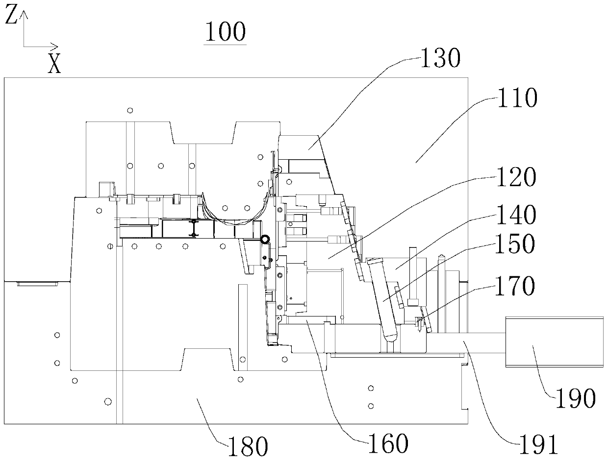
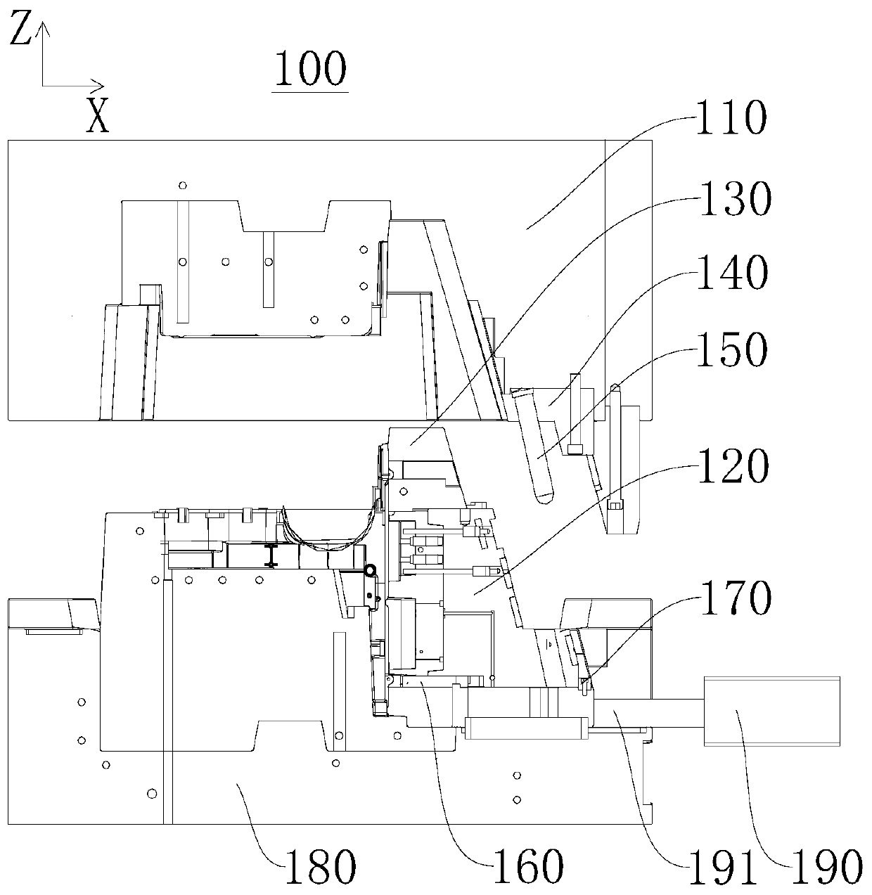
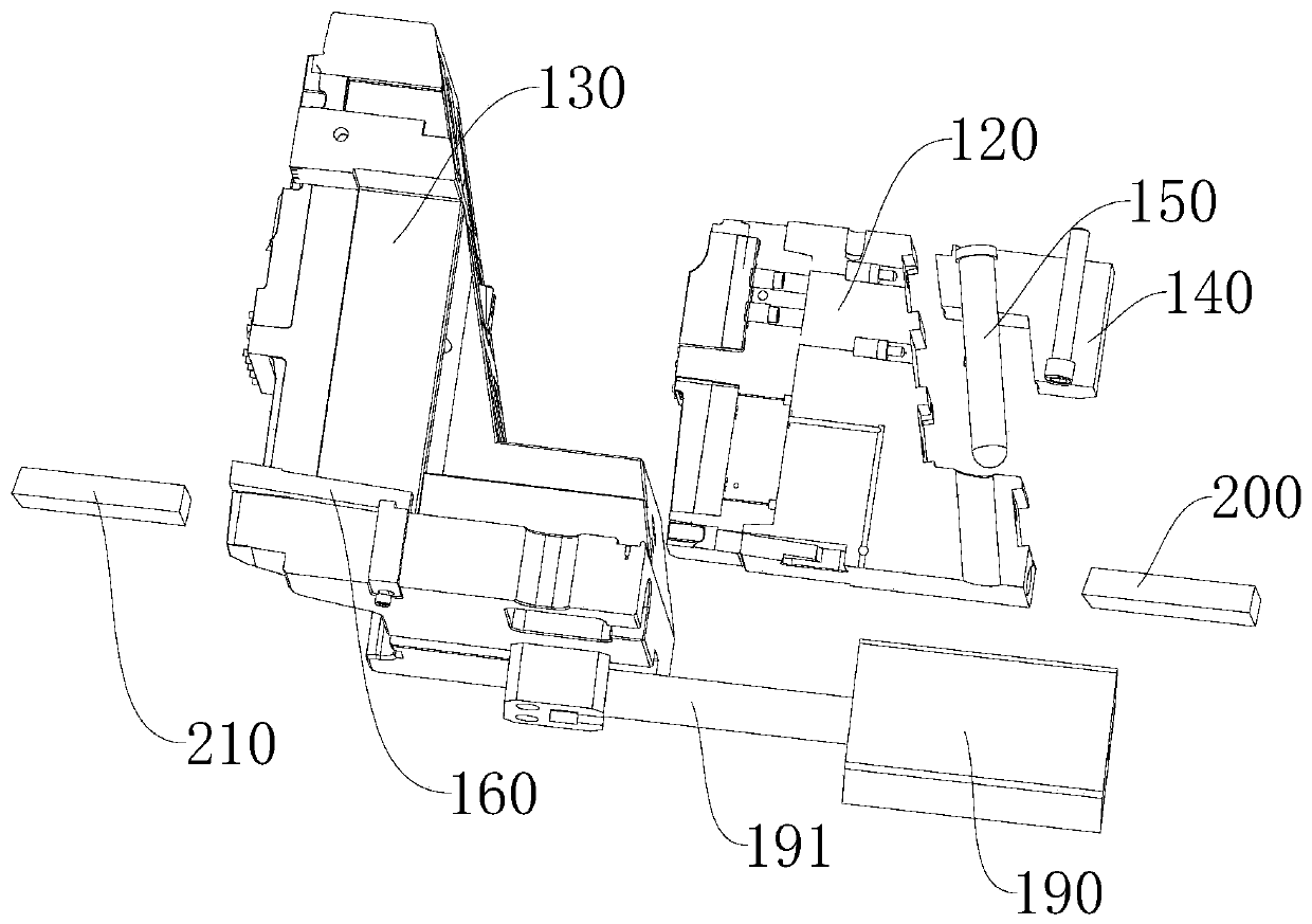
[0028] Please refer to figure 1 , figure 2 , image 3 and Figure 4 , the embodiment of the present invention provides a slider inclined top core-pulling mechanism 100, which is used for core-pulling molding of products. It can complete the core-pulling work in multiple directions at one time, shorten the molding cycle, reduce equipment costs and labor costs, and the movement process is stable and reliable, and the product quality is high. In this embodiment, the sliding block inclined top core-pulling mechanism 100 is used for core-pulling the ribs on the product and the side holes opened on the side of the ribs. The direction is vertical, and the slider inclined top core-pulling mechanism 100 can simultaneously perform core-pulling molding in these two directions.

[0029] The slider inclined top core-pulling mechanism 100 includes a fixed template 110, a first slider 120, a second slider 130, a shovel base 140, an inclined guide column 150, an inclined top core-pulling...

no. 2 example

[0040] Please refer to Figure 9 , the present invention provides an injection mold 10 for producing plastic products. The injection mold 10 includes a slider inclined top core-pulling mechanism 100 , a fixed mold seat plate 300 and a movable mold seat plate 400 . Among them, the basic structure, principle and technical effect of the slider inclined top core-pulling mechanism 100 are the same as those of the first embodiment. For a brief description, the part not mentioned in this embodiment can refer to the corresponding content in the first embodiment. .

[0041] In this embodiment, the fixed mold base plate 300 is connected to the side of the fixed platen 110 away from the movable platen 180, the movable mold base plate 400 is connected to the side of the movable platen 180 away from the fixed platen 110, and the fixed mold base plate 300 is fixedly connected to the pressure On one side of the machine, the movable die seat plate 400 is fixedly connected to the other side ...


PUM


Abstract

The invention discloses a sliding block ramp-roof core pulling mechanism and an injection mold, and relates to the technical field of molds. The sliding block ramp-roof core pulling mechanism comprises a fixed mold plate, s first sliding block, a second sliding block, a shovel base, a ramp guide column and a ramp-proof core pulling assembly. The shovel base is fixedly installed on the fixed mold plate. The ramp guide column is fixedly connected with the shovel base, and is in sliding fit with the first sliding block. The first sliding block is in sliding connection with the second sliding block. A ramp roof is in sliding connection with the guide base. The guide base is fixedly installed on the second sliding block. A guide groove is formed in the first sliding block. The ramp roof is arranged in the guide groove in a sliding manner. Compared with the prior art, according to the sliding block ramp-roof core pulling mechanism, because the first sliding block in sliding connection with the second sliding block is adopted, and the ramp proof arranged in the guide groove in the sliding manner is adopted, the core pulling work in multiple directions can be completed at one time, the molding cycle is shortened, the equipment cost and the labor cost are reduced, the motion process is stable and reliable, and the product quality is high.

Description

technical field [0001] The invention relates to the technical field of moulds, in particular to a slider inclined top core-pulling mechanism and an injection mold. Background technique [0002] At present, in the application of plastic molds, for the situation that there are ribs on the side of the product and holes are set on the ribs, since the movement direction of the traditional slider can only be a single direction, it is difficult to use the slider mechanism alone to form the core at one time. , the current solution is to process the product multiple times and use a variety of mechanisms to form it, but in this way, the process is difficult, the forming cycle is long, and the cost of equipment and labor is high. Contents of the invention [0003] The problem solved by the invention is how to complete the core-pulling work in multiple directions at one time, shorten the molding cycle, reduce the equipment cost and labor cost, and the movement process is stable and re...

Claims


Application Information

Patent Timeline
IPC IPC(8): B29C45/33
Inventor 王青坤何生成
Owner NINGBO AUX ELECTRIC
Why Eureka
Try Eureka